Printing apparatus

a printing apparatus and printing paper technology, applied in the direction of digital output to print units, instruments, visual presentations, etc., can solve the problems and failing to cope with elongation or contraction in the transport direction of printing paper, etc., to achieve the effect of lowering print quality and preventing lowering print quality

Active Publication Date: 2021-09-07
DAINIPPON SCREEN MTG CO LTD
View PDF7 Cites 1 Cited by
  • Summary
  • Abstract
  • Description
  • Claims
  • Application Information

AI Technical Summary

Benefits of technology

[0007]Some conventional apparatus, taking an elongation of web paper in the transport direction, for example, carry out back surface printing based on elongated image data for printing on the back surface. Even with such conventional apparatus, however, the back surface printing is stopped by a page length of the web paper detected by a sensor of a back surface printing device. An elongated image on the back surface is therefore cut halfway. Consequently, there is a problem, as with the foregoing apparatus, that a white streak will appear on the back surface, lowering print quality.
[0008]This invention has been made having regard to the state of the art noted above, and its object is to provide a printing apparatus which can prevent lowering of print quality due to an elongation or contraction of a printing medium by correcting back surface image data based on elasticity information on the printing medium.
[0011]According to this invention, after the front surface print head prints on the front surface of the printing medium the front surface image based on the surface image print data, the back surface image data corrector creates corrected back surface image data from the image size of the back surface image data based on the elasticity information. The back surface print head prints the corrected back surface image data on the back surface of the printing medium with reference to the cue mark. Thus, the back surface printing is carried out reflecting an elongation or contraction in the transport direction of the printing medium occurring with the front surface printing. This can prevent lowering of printing quality due to an elongation or contraction of the printing medium.
[0019]The notification given by the alarm of an error can prevent a continued printing carried out in a state of lowered accuracy of correcting the back surface image data.
[0021]Also when a plurality of lanes are set in the width direction of the printing medium and a different image is printed in each lane, the back surface image data corrector creates the corrected back surface image data for each lane. Thus, the printing with the plurality of lanes can also prevent lowering of printing quality due to elongation or contraction of the printing medium.

Problems solved by technology

However, the conventional example with such construction has the following problems.
That is, the conventional apparatus can cope with the elongation and contraction in the width direction of the printing paper, but has a problem of failing to cope with an elongation or contraction in a transport direction of the printing paper.
Such a white streak is about 0.1-0.2 mm, for example, but is very conspicuous, which poses a problem of lowering print quality.
Even with such conventional apparatus, however, the back surface printing is stopped by a page length of the web paper detected by a sensor of a back surface printing device.
Consequently, there is a problem, as with the foregoing apparatus, that a white streak will appear on the back surface, lowering print quality.

Method used


Image

  • Printing apparatus
  • Printing apparatus
  • Printing apparatus

Examples


embodiment 1

[0034]Embodiment 1 of this invention will be described hereinafter with reference to the drawings.

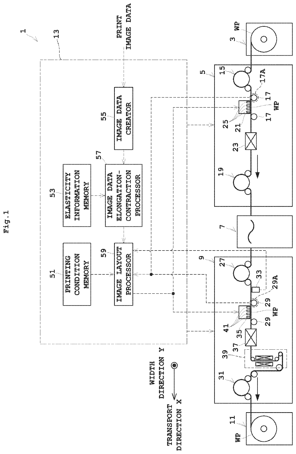
[0035]FIG. 1 is an outline view showing an entire inkjet printing apparatus according to Embodiment 1.

[0036]The inkjet printing apparatus according to this embodiment includes a paper feeder 3, a front surface printing unit 5, an inverting unit 7, a back surface printing unit 9, a takeup roller 11, and a printing control unit 13.

[0037]The paper feeder 3 holds a roll of web paper WP to be rotatable about a horizontal axis. The paper feeder 3 unwinds the web paper WP to feed it in a transport direction X to the front surface printing unit 5. The takeup roller 11 winds up into a roll form around a horizontal axis the web paper WP printed on the two surfaces thereof by the front surface printing unit 5 and back surface printing unit 9.

[0038]The web paper WP noted above corresponds to the “printing medium” in this invention.

[0039]The front surface printing unit 5 has a drive roller 15 locate...

embodiment 2

[0062]Next, Embodiment 2 of this invention will be described with reference to the drawings.

[0063]FIG. 4 is an outline view showing an entire inkjet printing apparatus according to Embodiment 2. Components having the same functions are shown with the same signs, and will not particularly be described.

[0064]This embodiment is different from foregoing Embodiment 1 in that the back surface printing unit 9 of an inkjet printing apparatus 1A has a page interval calculator 61.

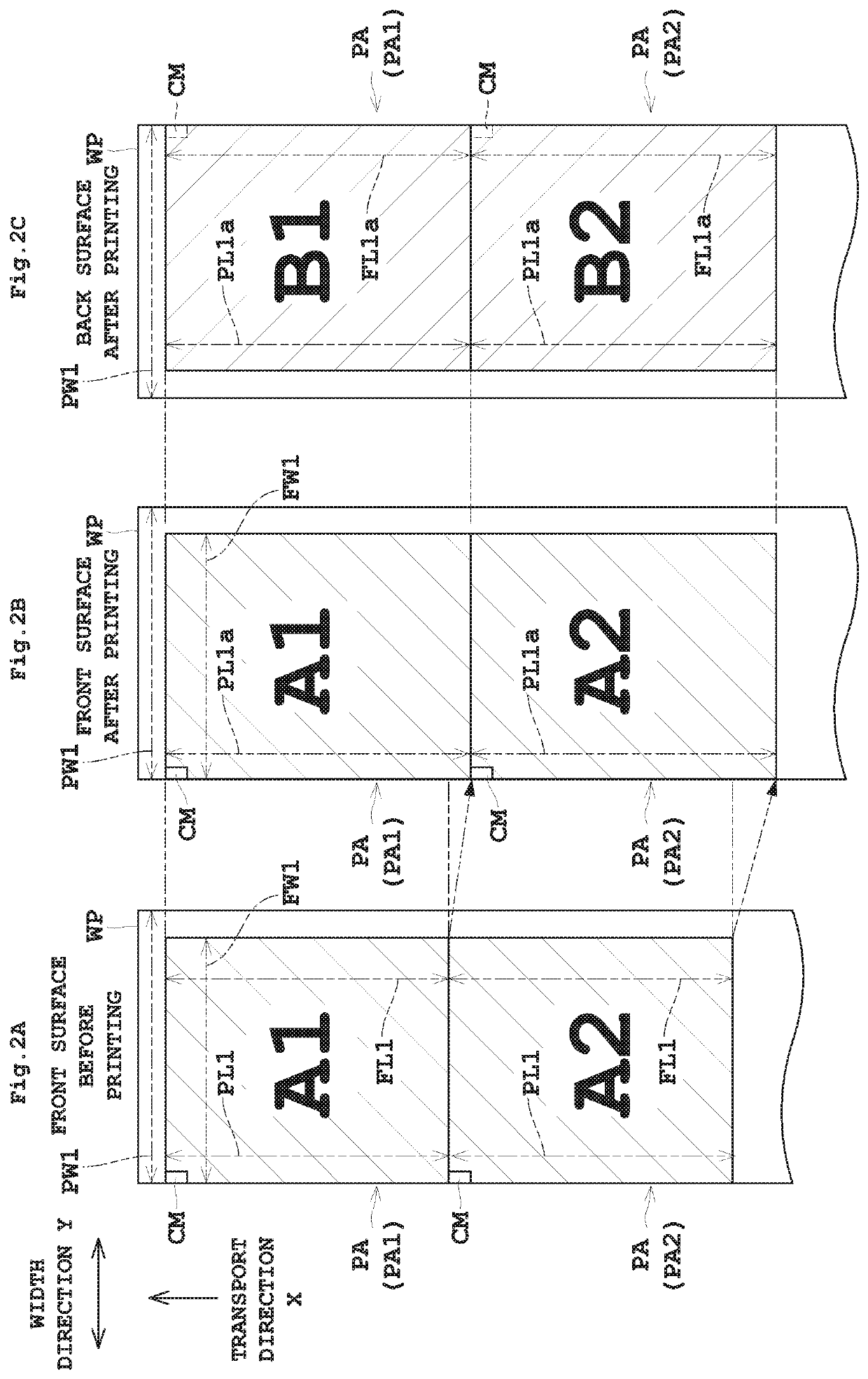
[0065]The page interval calculator 61 calculates a length in the transport direction X between the cue mark CM and the next cue mark CM printed on the front surface of the web paper WP. That is, the page interval calculator 61 calculates an interval between the cue marks CM based on the signal from the encoder 29A representing a count from when the detector 33 detects the first cue mark CM until when the detector 33 detects the next cue mark CM. This interval becomes equal to the print area length PL1a after the fron...

embodiment 3

[0069]Next, Embodiment 3 of this invention will be described with reference to the drawings.

[0070]FIG. 5 is an outline view showing an entire inkjet printing apparatus according to Embodiment 3. Components having the same functions are shown with the same signs, and will not particularly be described.

[0071]This embodiment is different from foregoing Embodiment 1 in that the back surface printing unit 9 of an inkjet printing apparatus 1B has the page interval calculator 61, a cut limiting value memory 71, a cut amount arithmetic processor 73, an error checker 75, and an alarm 77

[0072]The page interval calculator 61 has the same function as in foregoing Embodiment 2. The cut limiting value memory 71 stores beforehand a limiting value of any excess or deficiency occurring when printing is carried out based on the corrected back surface image data. The cut amount arithmetic processor 73 calculates a difference between the interval between the cue marks CM calculated by the page interval...


PUM


Abstract

A printing apparatus for printing on a front surface of a printing medium, and thereafter printing on a back surface of the printing medium. The apparatus includes the following elements: a front surface print head for printing a cue mark, and printing a front surface image based on front surface image data with reference to the cue mark; a back surface image data corrector for creating corrected back surface image data based on elasticity information in a transport direction after printing of the front surface image; a detector for detecting the cue mark; and a back surface print head for printing the corrected back surface image data on the back surface of the printing medium with reference to the cue mark detected by the detector.

Description

BACKGROUND OF THE INVENTION(1) Field of the Invention[0001]This invention relates to a printing apparatus for printing on the back surface after printing on the front surface of a printing medium, and more particularly to a technique of registering images on the back and front surfaces.(2) Description of the Related Art[0002]Conventionally, a known apparatus of this type includes a paper information acquiring unit, a front surface printing condition information acquiring unit, a register information creating unit, and a back surface printing unit (see Japanese Unexamined Patent Publication No. 2014-144608, for example). The paper information acquiring unit acquires paper information as information on printing paper. The front surface printing condition information acquiring unit acquires front surface printing condition information. The register information creating unit creates, based on the paper information and front surface printing condition information, register information in...

Claims


Application Information

Patent Timeline
Patent Type & Authority Patents(United States)
IPC IPC(8): B41J3/60G06F3/12B41J11/00B41J13/03B41J13/00B41J29/38B41J11/46
CPCB41J3/60B41J11/008B41J11/0095B41J11/46B41J13/0027B41J13/03B41J29/38G06F3/1208B41J15/04G06K15/021G06K15/1868G06F3/1251G06F3/1282
Inventor TAKAHASHI, SUSUMU
Owner DAINIPPON SCREEN MTG CO LTD
Why Eureka
Try Eureka