
Depth adjustable hub for use with abrasive grinding tool

a grinding tool and hub technology, applied in the field of abrasive finishing articles, can solve the problems of grinding device not being able to touch the workpiece, grinding device cannot be used to grind, grinding device cannot be able etc., and achieve the effect of increasing the ability to withstand higher shear force and low area

Active Publication Date: 2021-09-21
GENERAL TOOLS
View PDF10 Cites 1 Cited by
  • Summary
  • Abstract
  • Description
  • Claims
  • Application Information

AI Technical Summary

Benefits of technology

[0007]The present invention utilizes a locking mechanism for the hub to attach and detach from the grinding device. For definitional purposes, the grinding cup without its hub will be called the body. The hub rests in the center of the grinding device and has appropriate slots to attach to the body. The hub of the invention attaches by rotating towards the direction of the spin created by the power tool. In the central area of the grinding device is a hole with the same dimensions as the hub and ribs that fit with the slots in the hub. The ribs have fillets on its sides to create a low area of stress which ultimately increases its ability to withstand higher shear forces.
[0009]After the ribs are inserted into the hub, the ribs slide into the cavities of the hub through rotation of the grinding device while the hub is fixed. The ribs in this position can only move towards the opposite direction of the initial rotation which is also the opposite rotating direction when the grinding device is in use. By rotating the grinding device in this direction opposite to the rotation during use, the grinding disc is free to move upwards and be the ribs are able to be removed from the hub. The grinding device then can be rotated to line up its ribs on another set of slots in the hub which changes the overall height of the grinding device and hub combination.

Problems solved by technology

Many times these devices create harmful dusts that must be removed using a dust shroud / vacuum combination.
But the height of the grinding device limits which dust shroud can be used because the two may not fit due to their height difference.
If the grinding device is shorter than that of the dust shroud, then the dust shroud will create a seal with the workpiece but the grinding device will be unable to touch the workpiece and grind.
And even though the grinding apparatus may fit with the dust shroud, the grinding apparatus can become worn, which alters their overall height.
This causes the grinding apparatus to no longer work with the dust shroud due to the height difference.
The hubs are also time consuming to remove as the grinding device must be removed from the power tool and the hubs must be screwed off and replaced.

Method used


Image

  • Depth adjustable hub for use with abrasive grinding tool
  • Depth adjustable hub for use with abrasive grinding tool
  • Depth adjustable hub for use with abrasive grinding tool

Examples


Embodiment Construction

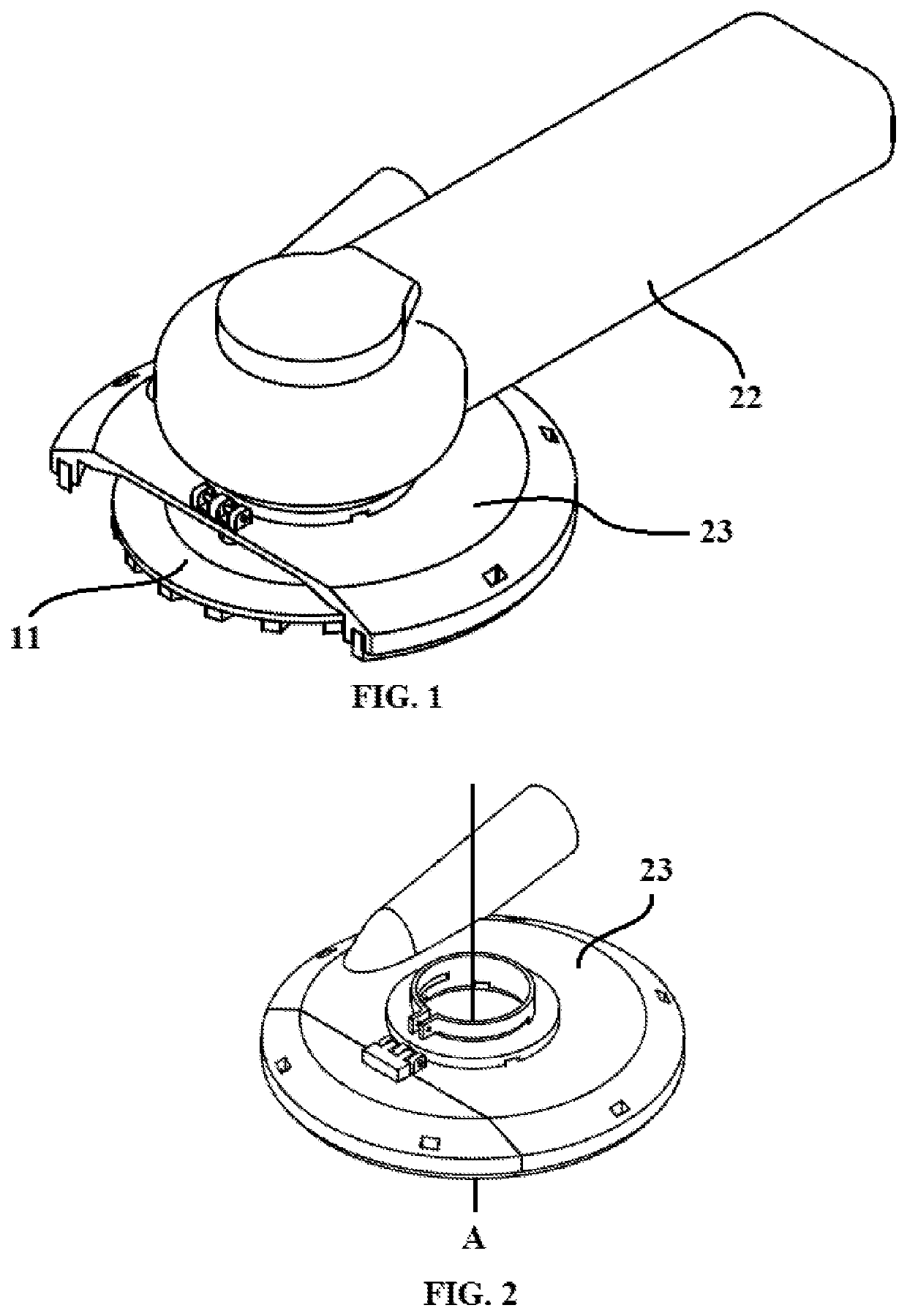
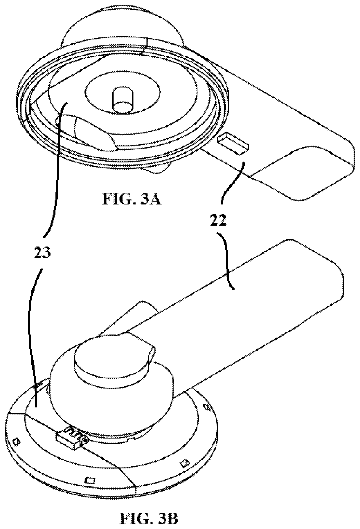
[0021]As shown in FIG. 1, a grinding tool device generally comprises a rotary tool 22 that is associated with a grinding cup 11 surrounded by a protective housing, such as a dust shroud 23 like the one depicted in FIGS. 2, 3A and 3B.

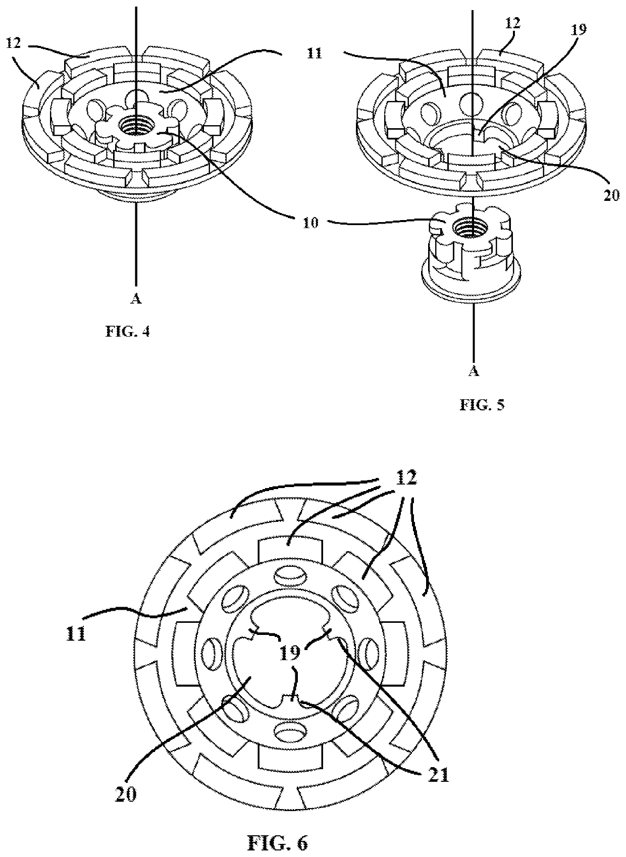
[0022]According to the present invention, as shown in FIG. 4, the grinding device of the present invention comprises a grinding wheel 11 and associated wheel hub 10. The grinding wheel 11 comprises a plurality of grinding segments 12, such as metal and / or diamond containing segments, which are used to grind or polish a surface, such as a concrete surface.

[0023]As shown in FIGS. 5 and 6, the grinding wheel 11 includes a plurality of ribs 19 (such as two or more or three or more) that extend from the aperture 20 of the wheel towards the center of the wheel. The hub 10 is attached to the wheel 11 by inserting the hub 10 into the wheel aperture 20 and lining up the ribs 19 on the wheel 11 with the appropriate slots 13 on the hub 10. The complete assembly pro...


PUM


Abstract

An abrasive finishing article with an adapter or hub to attach to an appropriate power tool, wherein the hub contains sets of slots to receive ribs positioned on a grinding wheel to permit adjustment of the height of the hub to change the overall height of the grinding wheel and abrasive finishing article.

Description

CROSS REFERENCE TO RELATED APPLICATIONS[0001]This non-provisional application claims the benefit under 35 U.S.C. § 119(e) to U.S. Provisional Application No. 62 / 510,105, filed on May 23, 2017, all of which are hereby expressly incorporated by reference into the present application.FIELD OF THE INVENTION[0002]The invention relates to abrasive finishing article with an adapter or hub to attach to an appropriate power tool. More specifically, the invention provides a hub to permit adjustment of the height of the hub to change the overall height of the abrasive finishing article and for the hub to be detached through a rotating motion.BACKGROUND OF THE INVENTION[0003]Abrasive grinding devices are commonly used to grind the surface of various materials. Many times these devices create harmful dusts that must be removed using a dust shroud / vacuum combination. But the height of the grinding device limits which dust shroud can be used because the two may not fit due to their height differen...

Claims


Application Information

Patent Timeline
Patent Type & Authority Patents(United States)
IPC IPC(8): B24D7/16B24B23/02B24B45/00B24B55/10F16B21/02
CPCB24D7/16B24B23/022B24B45/006B24B55/102F16B21/02
Inventor PARK, JOON HO
Owner GENERAL TOOLS
Learn More