Data recovery method for RAID system

a data recovery and raid system technology, applied in the field of storage technology, can solve the problems of taking a substantial time to read data from and write data to the drives, and still taking about an hour to read and write data, so as to reduce the time for data recovery

Active Publication Date: 2021-09-21
ACCELSTOR TECH LTD
View PDF11 Cites 0 Cited by
  • Summary
  • Abstract
  • Description
  • Claims
  • Application Information

AI Technical Summary

Benefits of technology

[0007]In conclusion, the RAID system and the data recovery method for same provided in the embodiments of the present disclosure can reduce data recovery time.

Problems solved by technology

Because the drives have large capacities, it will take a substantial time to read data from and write data to the drives.
However, for example, if the capacity of a single drive is 2 TB, it still takes about one hour to read and write data.

Method used


Image

  • Data recovery method for RAID system
  • Data recovery method for RAID system
  • Data recovery method for RAID system

Examples


first embodiment

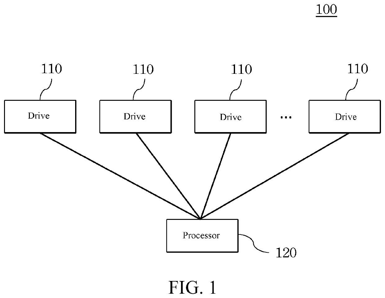
[0015]FIG. 1 is a schematic architectural diagram of a RAID system 100 according to the present disclosure. The RAID system 100 includes a plurality of drives 110 and a processor 120 connected to the drives 110, and in addition further includes an access interface, a memory, and the like. Details are not described herein. The drive 110 may be a conventional hard disk drive (HDD) or an SSD. The processor 120 is a processing unit capable of executing computer instructions and performing operations.

[0016]Referring to Table 1, a RAID that is formed by eight drives 110 (D1 to D8) is used for description. Herein, for example, the RAID is a RAID level 4. However, the present invention is not limited thereto. The drives 110 may be alternatively applied to a RAID level 5 or even a RAID level 6. Herein, the drive D8 is a parity drive. The drives D1 to D8 form a plurality of data strips over the drives D1 to D8 through stripping processing. Herein, six data strips are used as an example for de...

second embodiment

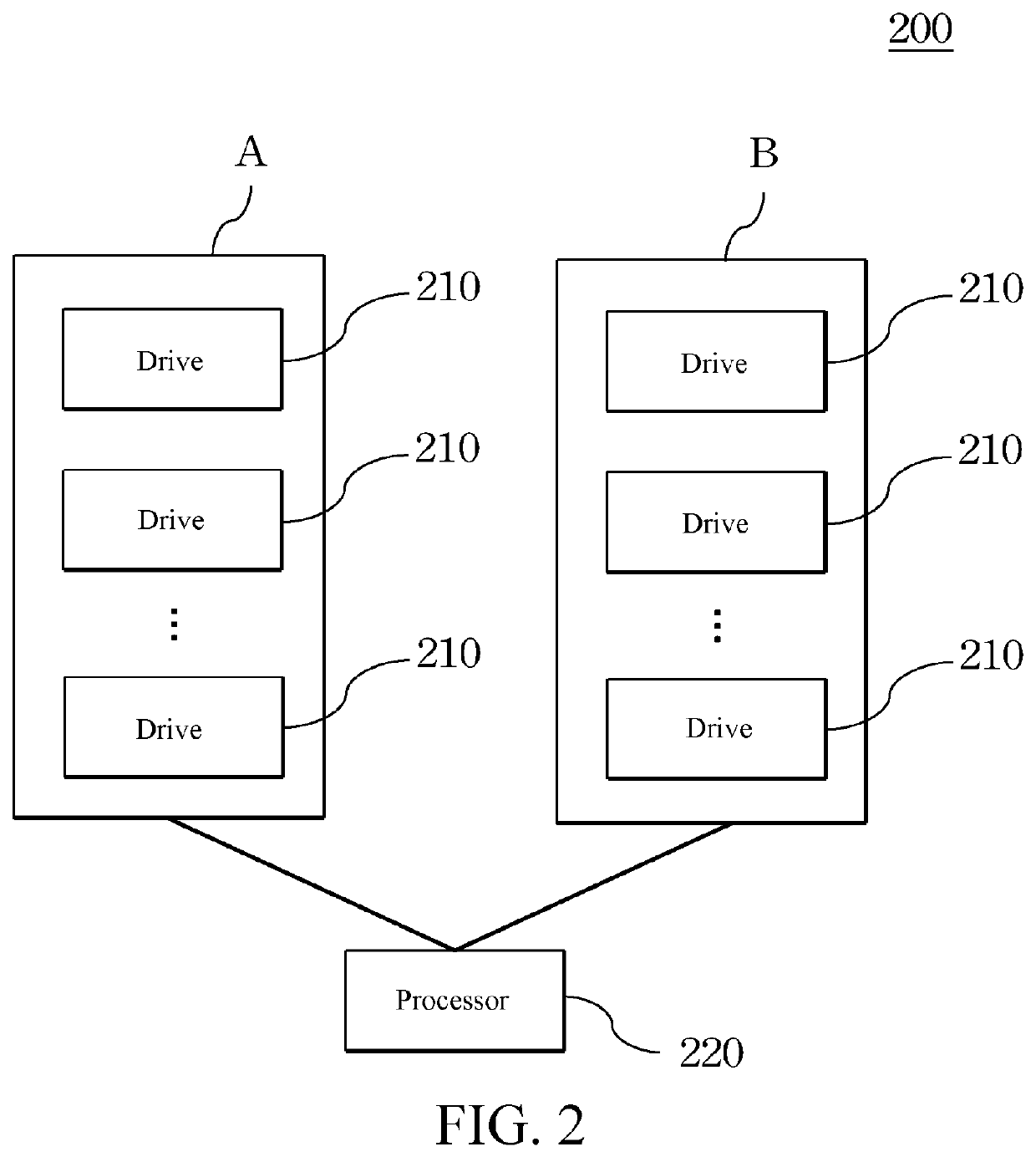
[0025]FIG. 2 is a schematic architectural diagram of a RAID system 200 according to the present disclosure. The RAID system 200 includes a plurality of drives 210 and a processor 220 connected to the drives 210, and in addition further includes an access interface, a memory, and the like. Details are not described herein. The drive 210 may be a conventional HDD or an SSD. The processor 220 is a processing unit capable of executing computer instructions and performing operations. Herein, the drives 210 are grouped into two groups, one group of drives 210 form a first RAID A, and the other group of drives 210 form a second RAID B.

[0026]Referring to Table 3, one RAID that is formed by eight drives 210 (D1 to D8) and one RAID that is formed by eight drives 210 (D9 to D16) are used for description. Herein, for stripping and log-based writing in a RAID, refer to the description of the foregoing first embodiment. Details are not repeated herein again. Data is stored on data strips S1 and S...

third embodiment

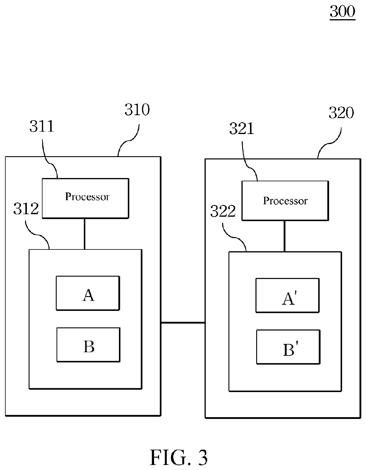
[0033]FIG. 3 is a schematic architectural diagram of a RAID system 300 according to the present disclosure. The RAID system 300 is a high availability (HA) cluster. That is, the RAID system 300 includes a first RAID 310 and a second RAID 320 that are mirrors of each other. The first RAID 310 include a first data pool 312 and a processor 311 connected to the first data pool 312. The first data pool 312 includes the foregoing first RAID A and second RAID B. Therefore, the stored data is the same as that listed in Table 3. The second RAID 320 includes a second data pool 322 and a processor 321 connected to the second data pool 322. The second data pool 322 includes a first RAID A′ that stores data the same as that in the first RAID A, and a second RAID B′ that stores data the same as that in the second RAID B. The data is therefore not otherwise listed. In some embodiments, each of the first data pool 312 and the second data pool 322 may alternatively include only one RAID. In some emb...


PUM


Abstract

A data recovery method for a Redundant Array of Independent Disks (RAID) system is provided. The RAID system includes a plurality of drives and a processor. Each drive includes a plurality of data pages. The drives form a plurality of data strips over the drives through stripping processing. Each data strip includes one of the data pages of every drive. The processor writes data to the data strips in a log-based manner and records whether each data page of each data strip is valid or invalid. During recovery of data from a broken one of the drives, data is recovered from a corresponding valid or written data page but is not recovered from a corresponding invalid or blank data page.

Description

CROSS-REFERENCE TO RELATED APPLICATION[0001]This non-provisional application claims priority under 35 U.S.C. § 119(a) to Patent Application No. 108113680 filed in Taiwan, R.O.C. on Apr. 18, 2019, the entire contents of which are hereby incorporated by reference.BACKGROUNDTechnical Field[0002]The present disclosure relates to a storage technology, and in particular, to a data recovery method for a RAID system.Related Art[0003]In an existing Redundant Array of Independent Disks (RAID), after a drive is broken, it takes time to read data to calculate parity bits to recover data from the broken drive. The recovered data is then written to a replacement drive. Because the drives have large capacities, it will take a substantial time to read data from and write data to the drives. With existing solid-state drives (SSD), the time of reading and writing data is reduced, and a maximum read / write speed may be up to 500 MB / s. However, for example, if the capacity of a single drive is 2 TB, it ...

Claims


Application Information

Patent Timeline
Patent Type & Authority Patents(United States)
IPC IPC(8): G06F11/00G06F11/20G06F11/10
CPCG06F11/2094G06F11/1076G06F11/1088G06F11/1092G06F2201/82
Inventor TSAO, SHIH-CHIANGCHIEN, TING-FANG
Owner ACCELSTOR TECH LTD
Why Eureka
Try Eureka