Magnetic storage systems and methods allowing for recovery of data blocks written off-track with non-constant offsets

Inactive Publication Date: 2009-04-21
MAXTOR
View PDF11 Cites 9 Cited by
  • Summary
  • Abstract
  • Description
  • Claims
  • Application Information

AI Technical Summary

Benefits of technology

[0030]Therefore, embodiments of the present invention may enhance the reliability of a magnetic storage system, such as a disk drive, by allowing for the recovery of data blocks written off-track with non-constant offsets. Also, embodiments of the present invention may provide for greater intelligence and less redundancy than related art magnetic storage systems by determining whether a dat

Problems solved by technology

Users of disk drives often store important data that would be costly to replace or recreate if lost or corrupted.
Despite the efforts of disk drive manufacturers, some types of data read errors, such as those caused by non-constant off-track write events, still persist that cannot be remedied with the related art data recovery procedures.
Even under vibration free conditions, there may still be some internal factors that can cause misalignment of a head with respect to a track center.
When operating in various environments, a disk drive may be subject to external forces in the form of vibrations or shocks.
When a head is positioned away from a track center, such misalignment may lead to an off-track read or an off-track write.
When there is an off-track read, the head may be unable to read data, without an error, from the track.
Related art disk error recovery measures have been unable to recover data blocks written off-track with non-constant offsets.
However, positioning a head at fixed offsets does not permit for reading data blocks that have been written off-track with non-constant offsets, because such data blocks do not have a fixed offset value throughout an entire data sector.
As a result, related art data recovery procedures have been ineffective in recovering data of data blocks written

Method used


Image

  • Magnetic storage systems and methods allowing for recovery of data blocks written off-track with non-constant offsets
  • Magnetic storage systems and methods allowing for recovery of data blocks written off-track with non-constant offsets
  • Magnetic storage systems and methods allowing for recovery of data blocks written off-track with non-constant offsets

Examples


Embodiment Construction

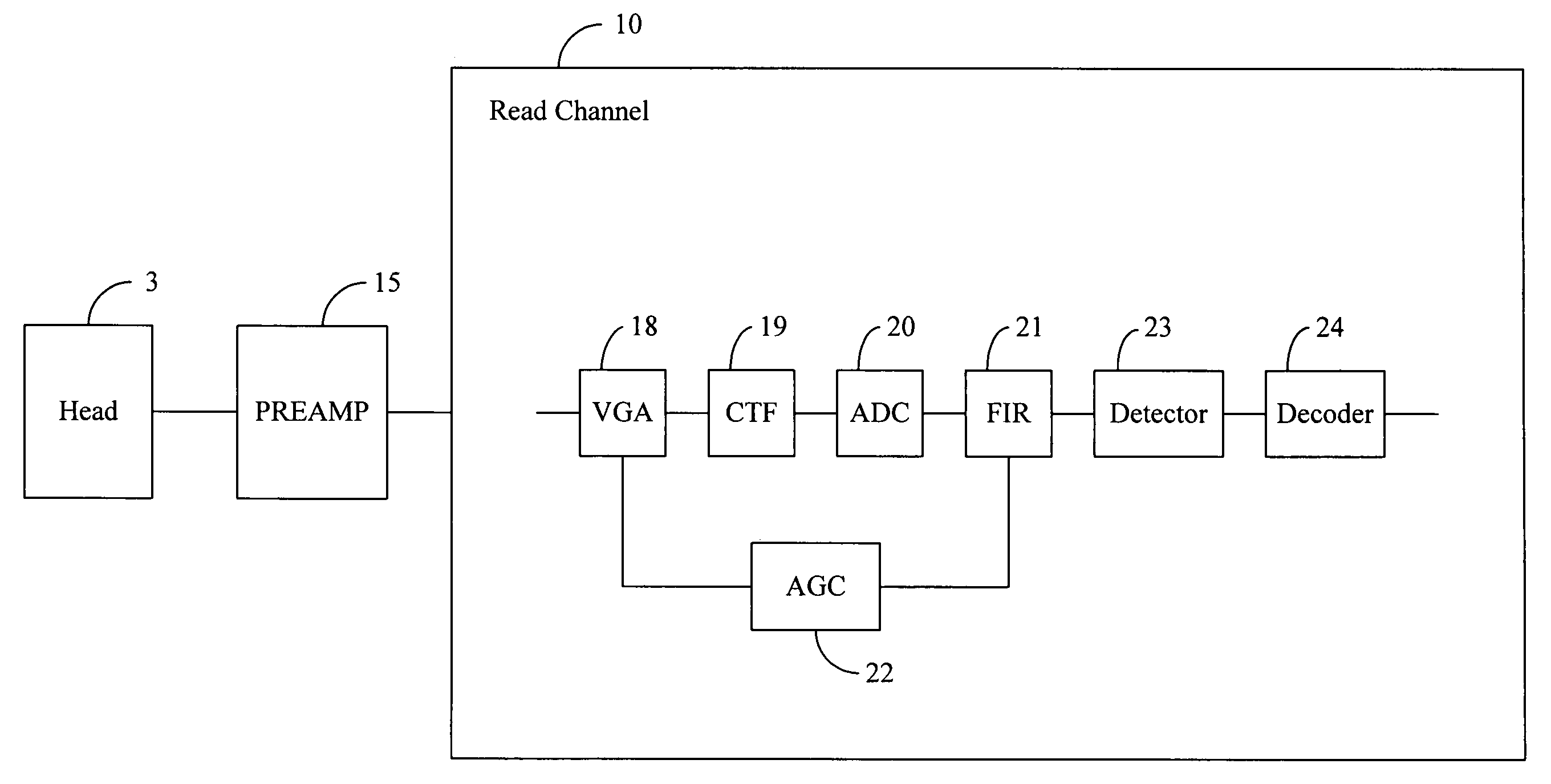
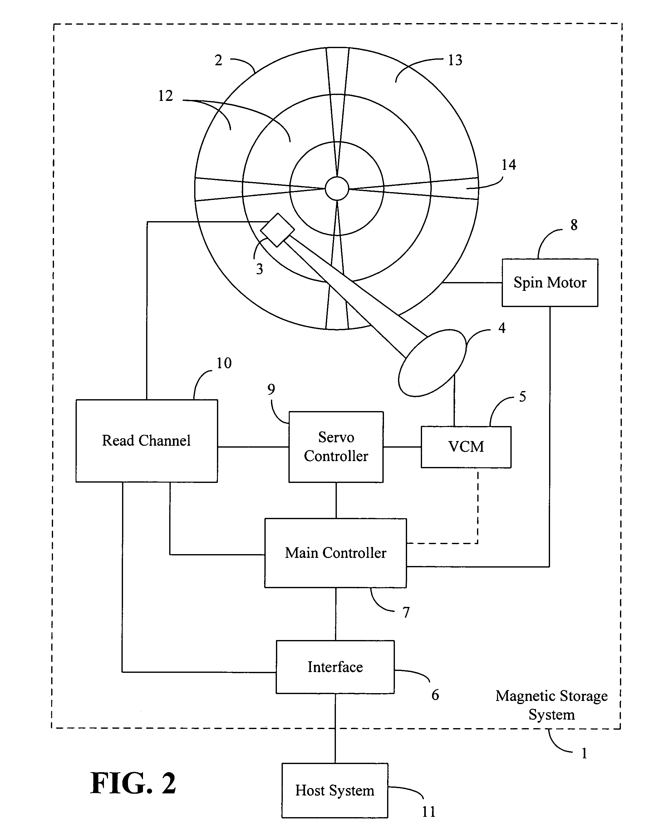
[0041]FIG. 2 illustrates a functional block diagram of a magnetic storage system 1 of an embodiment of the present invention. The magnetic storage system 1 comprises a disk 2, a transducer or head 3, an actuator 4, a voice coil motor (VCM) 5, an interface 6, a main controller 7, a spin motor 8, a servo controller 9, and a read channel 10. During operation, the disk 2 spins around a central axis, and the head 3 reads data from or writes data to a surface of the disk 2. The head 3 is supported on an arm of the actuator 4, and the VCM 5 rotates the actuator 4 about an axis in order to control a position of the head 3 over the disk 2.

[0042]The magnetic storage system 1 is not limited to having only a single disk 2, but may have a plurality of disks. Also, data may be written to both a top surface and a bottom surface of each disk, in which case a different head is required for each surface. The head 3 may have a single element for performing both reading and writing, or the head 3 may h...


PUM


Abstract

A magnetic storage system includes a disk, a head, an actuator, a read channel, and a main controller. The main controller causes the head to read a data block of a selected track of the disk at each of a plurality of fixed offsets from a center of the selected track. The main controller samples a gain in the read channel a plurality of times while the head is reading the data block at each of the plurality of fixed offsets to obtain a plurality of gain samples for each of the plurality of fixed offsets. If the data block was written off-track with a non-constant offset, the main controller determines an approximate starting position and an approximate rate of change of an off-track deviation of the data block based on the plurality of gain samples for the plurality of fixed offsets.

Description

CROSS-REFERENCE TO RELATED PATENT APPLICATIONS[0001]Embodiments of the present invention relate to U.S. Provisional Application Ser. No. 60 / 624,745, filed Nov. 3, 2004, entitled “Inertial Off-track Recovery”, the contents of which are incorporated by reference herein and which is a basis for a claim of priority.BACKGROUND OF THE INVENTION[0002]1. Field of the Invention[0003]Embodiments of the present invention relate generally to magnetic storage systems and methods and, in specific embodiments, to a magnetic storage system including a head, a read channel, and a main controller, in which the main controller obtains a gain profile by sampling a gain in the read channel a plurality of times while the head is reading a data block at a plurality of fixed offsets, and the main controller determines an approximate starting position and an approximate rate of change of an off-track deviation of the data block based on the gain profile.[0004]2. Related Art[0005]Magnetic storage systems, su...

Claims


Application Information

Patent Timeline
IPC IPC(8): G11B5/09G11B27/36G11B5/03G11B5/58
CPCG11B5/012G11B19/045G11B20/10G11B2220/2516
Inventor CHEN, MICHAEL
Owner MAXTOR
Why Eureka
Try Eureka