Pneumatic tire

a pneumatic tire and tire technology, applied in the field of pneumatic tires, can solve the problems of insufficient steering stability and difficulty in achieving further weight reduction, and achieve the effects of suppressing the increase in carcass layer mass, reducing the weight of tires, and suppressing the degradation of rigidity and durability

Active Publication Date: 2021-10-05
THE YOKOHAMA RUBBER CO LTD
View PDF23 Cites 0 Cited by
  • Summary
  • Abstract
  • Description
  • Claims
  • Application Information

AI Technical Summary

Benefits of technology

[0004]The present technology provides a pneumatic tire including a belt layer, in which a carcass layer shares a function of the belt layer to achieve a single-ply belt layer by employing a curved carcass structure in which an angle of a carcass cord continuously changes in a tread region and side regions so that the pneumatic tire can maintain good steering stability and achieve reduction in tire weight.
[0006]In the present technology, when the tread region indicates a region corresponding to the belt width of the belt layer and the side region indicates a region inward of the tire radial direction with respect to the tire maximum width position, the carcass cords of the carcass layer are inclined with respect to the tire radial direction in the tread region, and at the same time, extend along the tire radial direction in the side region. The carcass cords of the carcass layer and the belt cords of the belt layer are arranged to cross with each other in the tread region. With this structure, the carcass layer can share the function of the belt layer, and the belt layer can be reduced to a single-ply layer as compared to the related-art pneumatic tire including the two belt layers. As a result, the reduction in tire weight can be achieved. Further, in the tread region, the structure in which the carcass cords and the belt cords cross with each other is employed. Thus, the rigidity of the tread portion can sufficiently be secured, and the good steering stability can be exerted.
[0007]Further, the cord angle in the carcass layer with respect to the tire circumferential direction is preferably set in the following manner. That is, the cord angle falls within a range from 10° to 75° in the tread central region corresponding to 80% of the center of the belt width of the belt layer, is gradually increased as approaching outward in the tire width direction with respect to the edge of the belt layer, and falls within a range from 85° to 90° in the side region. Thus, the carcass layer can sufficiently share the function as the belt layer. Further, the carcass cords are allowed to be gently changed in angle between the tread region and the side region, and hence the durability can be improved. More preferably, the cord angle preferably falls within a range from 15° to 70° and more preferably a range from 15° to 65° in the tread central region.
[0009]In the present technology, it is preferred that a cord count per unit width, which is 50 mm, for the carcass cords forming the carcass layer at least in the tread region be from twenty to seventy, and that a diameter of each of the carcass cords fall within a range from 0.2 mm to 1.5 mm. Thus, increase in mass of the carcass layer is suppressed, which contributes to reduction in weight of the tire. At the same time, degradation in rigidity and durability can be suppressed.
[0010]In the present technology, it is preferred that an intermediate rubber layer having a thickness from 0.2 mm to 2.0 mm be arranged between the carcass layer and the belt layer. Thus, degradation in out-of-plane flexural rigidity of the tread region can be complemented, and plane flexural rigidity of the tread region can be improved.
[0011]In the present technology, it is preferred that a belt reinforcing layer be provided outward in the tire radial direction of the belt layer. Thus, high-speed durability can be improved.

Problems solved by technology

However, from the perspective of wear resistance and durability, it is difficult to achieve further reduction in weight with the method of reducing the thickness of each portion of the tire.
However, when the belt layer is completely removed from the tread portion, there is a problem in that steering stability cannot sufficiently be secured.

Method used


Image

  • Pneumatic tire
  • Pneumatic tire
  • Pneumatic tire

Examples


examples

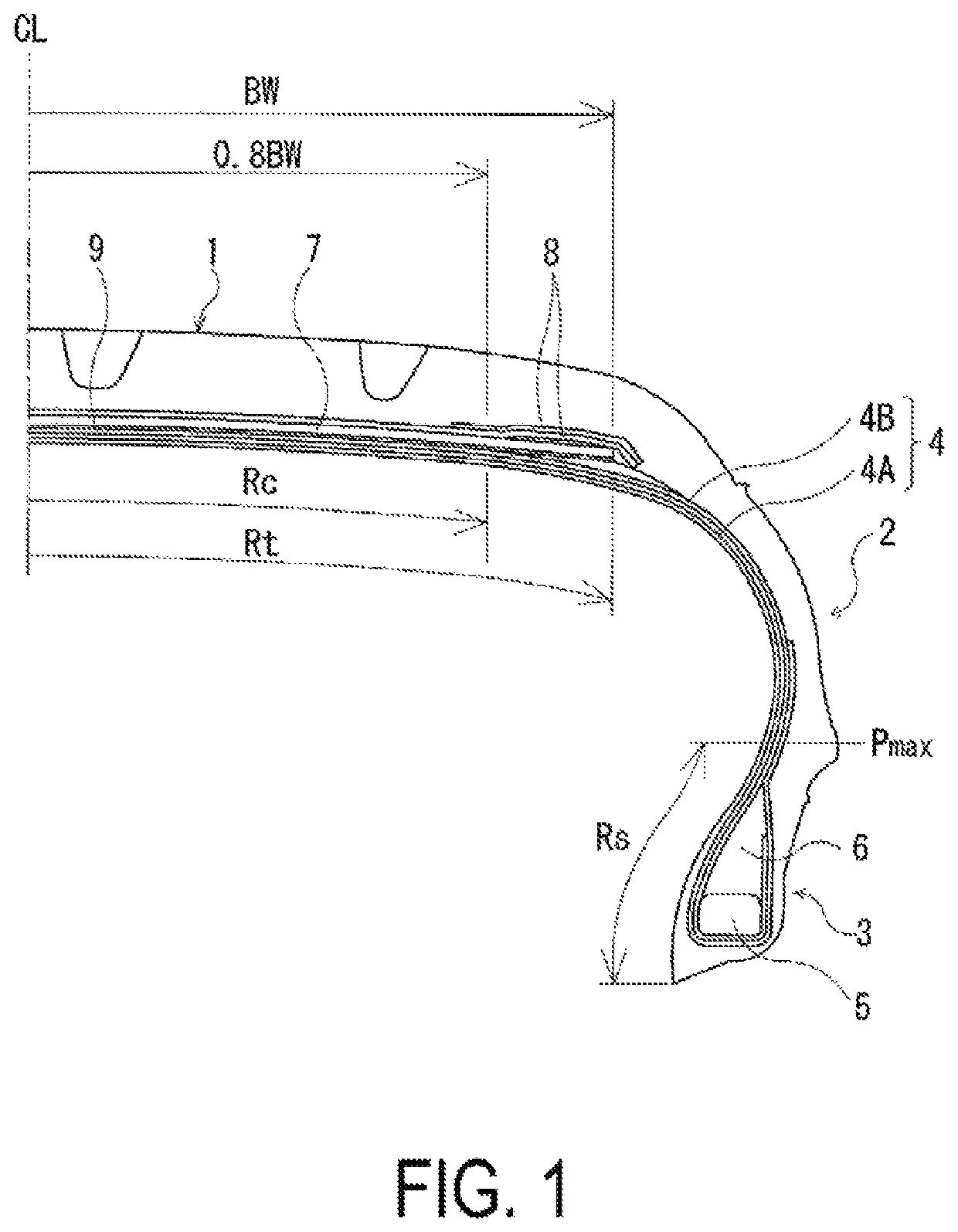
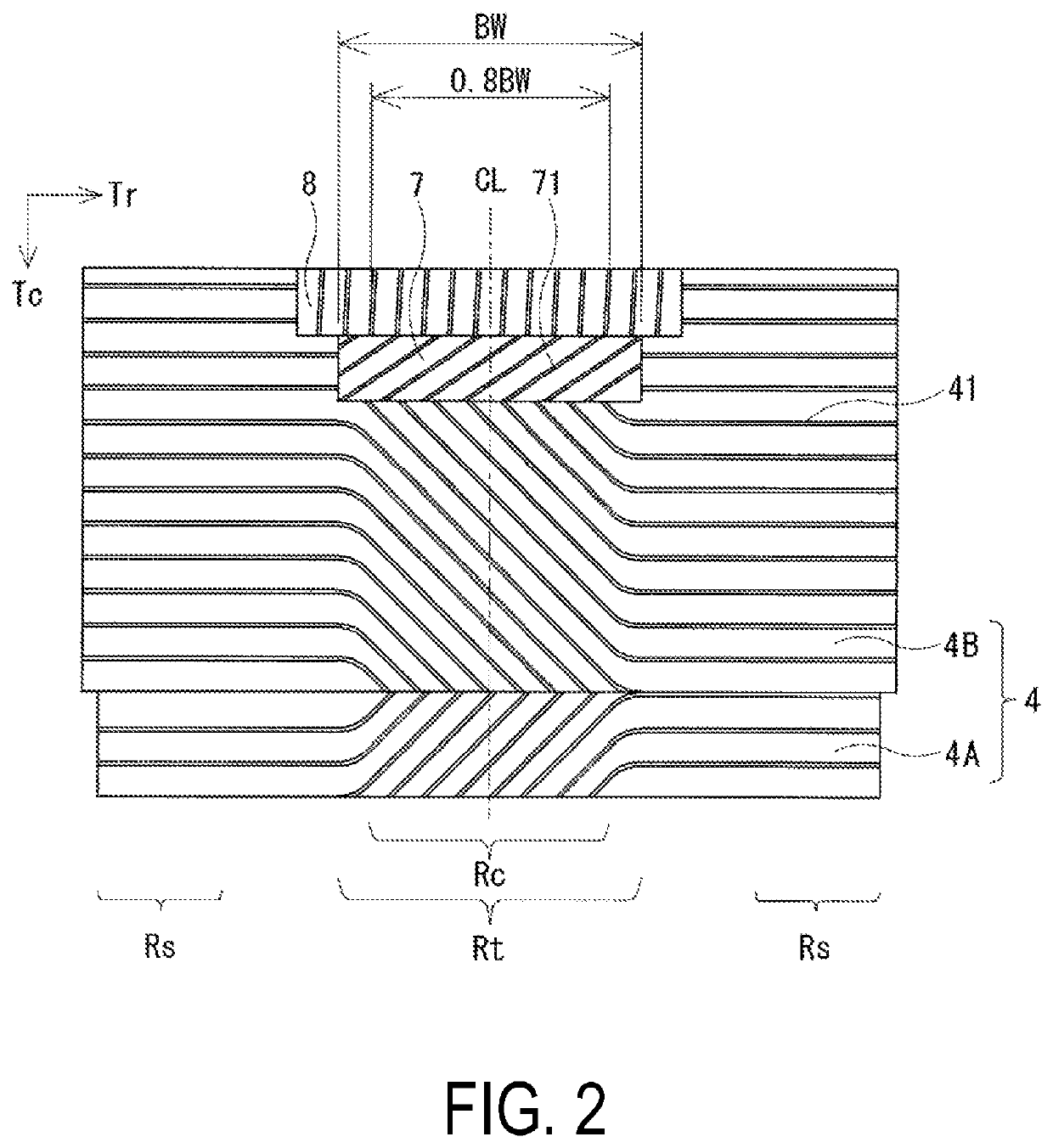
[0029]A tire for each of Examples 1 to 4 was manufactured in the following manner. The pneumatic tire had a tire size of 235 / 40R18, and included two carcass layers, and a single belt layer. The carcass layers included a plurality of carcass cords mounted between a pair of bead portions. The belt layer was positioned on an outer peripheral side of the carcass layers of a tread portion, and included a plurality of belt cords inclined with respect to a tire circumferential direction. Also, the carcass cords forming the carcass layers were inclined with respect to the tire radial direction in a tread region, and extended along the tire radial direction in a side region. The carcass cords forming the carcass layers and the belt cords forming the belt layer cross with each other in the tread region.

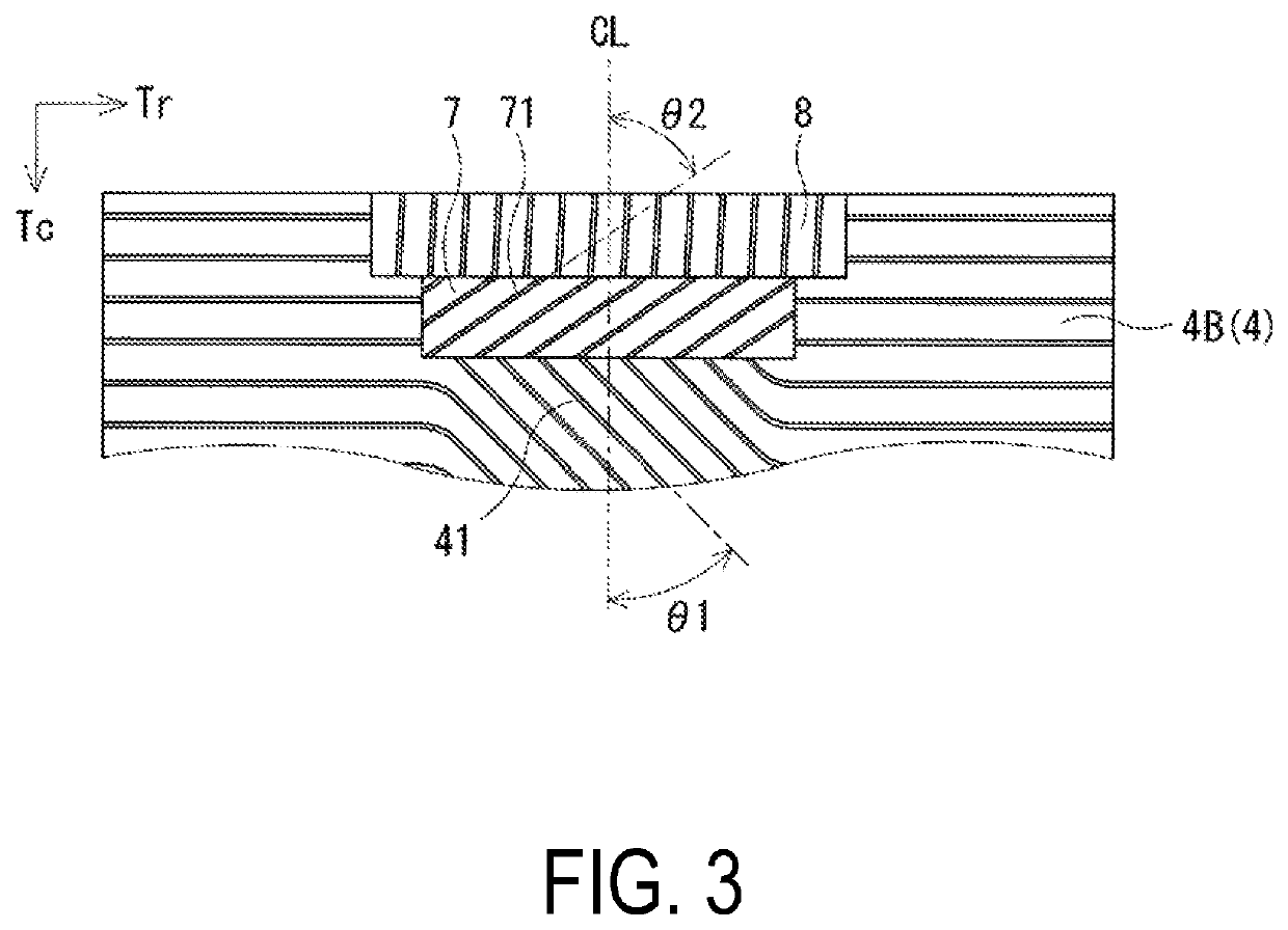
[0030]In each of Examples 1 to 4, as shown in Table 1, the cord angle in the inner carcass layer in the tread central region, the cord angle in the inner carcass layer in the side region, the c...


PUM


Abstract

Provided is a pneumatic tire including a belt layer. When the tread region indicates a region corresponding to a belt width of the belt layer and the side region indicates a region inward of a tire radial direction with respect to a tire maximum width position, the carcass cords forming the carcass layer are inclined with respect to the tire radial direction in the tread region, and at the same time, extend along the tire radial direction in the side region. The carcass cords forming the carcass layer and belt cords forming the belt layer cross with each other in the tread region.

Description

TECHNICAL FIELD[0001]The present technology relates to a pneumatic tire and more particularly relates to a pneumatic tire including a belt layer, in which a carcass layer shares a function of the belt layer to achieve a single-ply belt layer by employing a curved carcass structure in which an angle of a carcass cord continuously changes in a tread region and side regions so that the pneumatic tire can maintain good steering stability and achieve reduction in tire weight.BACKGROUND ART[0002]Generally, as a method of reducing weight of a tire, the thickness is reduced of rubber used for, for example, a cap tread and sides, which are portions of the tire large in area. However, from the perspective of wear resistance and durability, it is difficult to achieve further reduction in weight with the method of reducing the thickness of each portion of the tire.[0003]Meanwhile, for reduction in weight of the tire, there have been proposed various types of a tire which does not require an ind...

Claims


Application Information

Patent Timeline
Patent Type & Authority Patents(United States)
IPC IPC(8): B60C9/06B60C9/07B60C9/09B60C9/18B60C9/08B60C9/02B60C9/20B60C9/04
CPCB60C9/06B60C9/02B60C9/07B60C9/08B60C9/09B60C9/18B60C9/20B60C2009/0425B60C2009/2016B60C2009/2019Y02T10/86
Inventor MATSUDA, JUNSATOH, YUJIKODAMA, YUJI
Owner THE YOKOHAMA RUBBER CO LTD
Why Eureka
Try Eureka