Self-stowing cable dispenser for figure eighting

a self-stowing cable and figure eighting technology, which is applied in the direction of transportation and packaging, thin material processing, filament handling, etc., can solve the problems of the crew installing the line downtime, and achieve the effect of reducing the time to obtain the terminal end, rapid deployment, and reducing the downtime of the crew installing

Active Publication Date: 2021-10-05
TRIPLE C MFG
View PDF29 Cites 1 Cited by
  • Summary
  • Abstract
  • Description
  • Claims
  • Application Information

AI Technical Summary

Benefits of technology

[0006]We disclose a self-stowing cable dispensing mechanism to rapidly payout the reelable material in a figure eight formation. The cable dispensing mechanism retracts to a position that is compatible with the other functions of the reel lift assembly. For example, the stowed cable dispensing mechanism does not interfere with the reel lift assembly's ability to lift, carry, dispense, or retrieve the cable. The self-stowing cable dispensing mechanism may also decrease the time to obtain the terminal end of the cable by making the cable dispensing mechanism always available. For example, if the dispensing mechanism needs to be installed or brought over on a separate trailer, then each of those steps results in downtime for the crew installing the line. By self-stowing the cable dispensing mechanism, the dispensing mechanism can be rapidly deployed. By rapidly deploying a rapid dispensing solution, the total time to figure eight a cable may be dramatically reduced.
[0007]Another advantage of the current disclosure is that the cable dispensing mechanism can be positioned behind the reel with the reel in any vertical position. The primary arm is pivotally attached to the reel axle mount assembly so that the primary arm pivots about an axis parallel to the reel axle. By attaching the primary arm to the lifting arm, the primary arm moves relative to the lifting arm. The linear actuator pushes the slide along the longitudinal axis of the lifting arm. The slide drives the support to radially position the primary arm relative to the reel. The primary arm allows the cable dispensing mechanism to be positioned vertically relative to the pivot positions of the lifting arms. In this way, the cable can be dispensed in multiple reel lift positions.

Problems solved by technology

For example, if the dispensing mechanism needs to be installed or brought over on a separate trailer, then each of those steps results in downtime for the crew installing the line.

Method used


Image

  • Self-stowing cable dispenser for figure eighting
  • Self-stowing cable dispenser for figure eighting
  • Self-stowing cable dispenser for figure eighting

Examples


Embodiment Construction

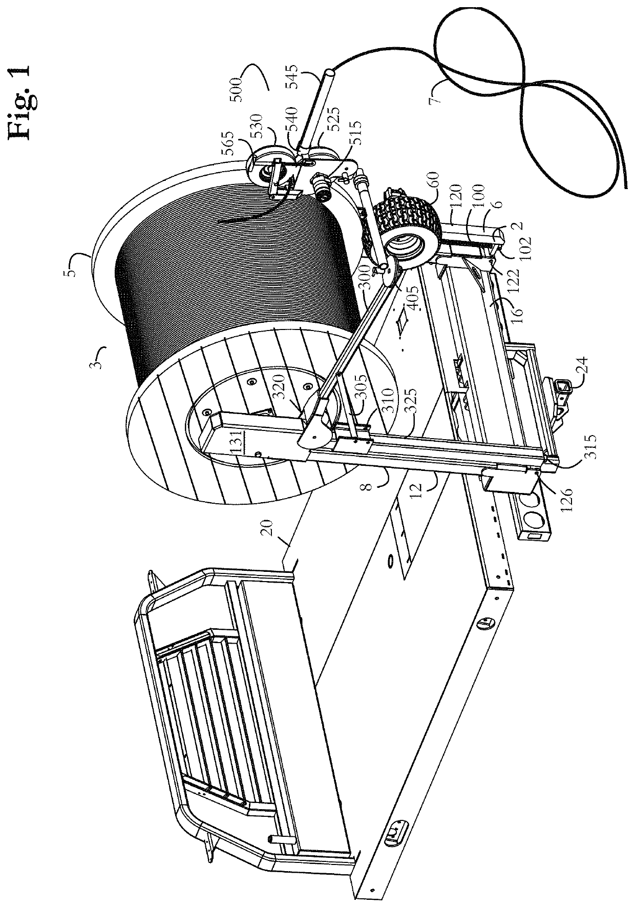
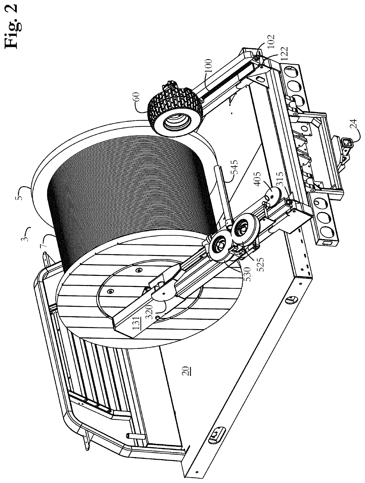
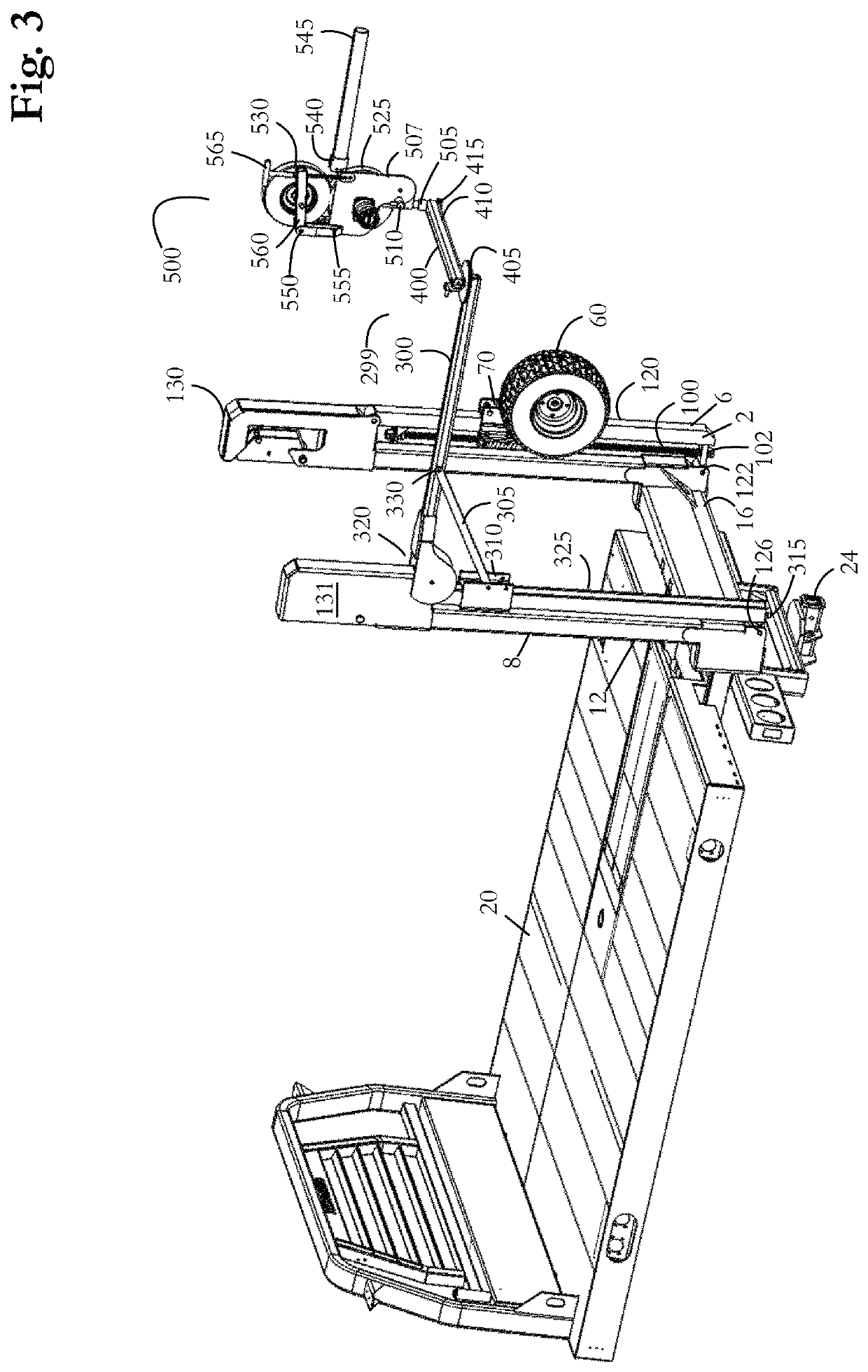
[0045]In order to dispense cable 7 from the reel 3, the motor assembly 500 is positioned on the dispensing side of the reel. As illustrated in FIG. 1, the reel lift apparatus has a first lifting arm 2 and a second lifting arm 8. The reel 3 is mounted to the free moving ends of the lifting arms with the reel axle extending between the first axle slot assembly 130 and the second axle slot assembly 131. The reel 3 may be raised above the vehicle bed 20, in the orientation shown in FIG. 1, with the lifting arms 2, 8 raised perpendicular to the vehicle bed 20.

[0046]To dispense the cable (or other reelable material), the payout arm 400 is pivoted to a horizontal position perpendicular to the primary arm 300. The motor assembly 500 is mounted to the free moving distal end of the payout arm 400. The motor assembly 500 is centrally positioned at a radial distance from the reel axle that extends between the first axle slot assembly 130 and the second axle slot assembly 131. The cable 7 (or ot...


PUM


Abstract

A method and apparatus for engaging a cable from a reel having a reel axle, such as for dispensing the cable from the reel with a motor assembly to figure eight a fiber optic cable sensitive to twisting. An adjustable frame is mounted to a first lifting arm. The adjustable frame is stored in a self-stowed configuration wherein the adjustable frame is vertically stacked parallel to the first lifting arm. The adjustable frame is deployed to align a distal frame end of the adjustable frame near the horizontal center of the reel in a plurality of lifting arm pivot positions.

Description

CROSS REFERENCES[0001]This application claims the benefit of U.S. Provisional Application No. 62 / 732,355, filed 17 Sep. 2019.FIELD OF THE INVENTION[0002]The present disclosure relates to devices for dispensing reelable material such as cable, wire, rope or other reelable material from a reel unit mounted on a vehicle adapted to transport and carry reel units on lifting arms. The present disclosure also relates to methods for dispensing the reelable material into a figure eight pattern to access a terminal portion of the reelable material.BACKGROUND OF THE INVENTION[0003]Self-loading bed assemblies for flat-bed trucks are useful for adapting a truck to pick-up, transport, and then feed or off-load one or more big round bales, as shown in U.S. Pat. No. 4,564,325. The actuating mechanism for the lifting arms is located underneath the bed, and the lift arms are designed to pivot between a stored position where the arms are positioned on the top surface of the bed and an extended positio...

Claims


Application Information

Patent Timeline
Patent Type & Authority Patents(United States)
IPC IPC(8): B65H57/18B65H75/30B65H49/34
CPCB65H57/18B65H49/34B65H75/30B65H49/321B65H49/325B65H49/327B65H2701/32
Inventor RUSSELL, JAY R.ACKERMAN, GALEN R.STRATHMAN, EDWIN J.
Owner TRIPLE C MFG
Why Eureka
Try Eureka