Image forming apparatus including varistor

a technology of image forming apparatus and varistor, which is applied in the direction of electrographic process apparatus, instruments, electrographic process, etc., can solve the problems of failure accompanied by scattering of parts, and failure to achieve the effect of increasing the size of the image forming apparatus

Active Publication Date: 2021-10-05
CANON KK
View PDF12 Cites 0 Cited by
  • Summary
  • Abstract
  • Description
  • Claims
  • Application Information

AI Technical Summary

Benefits of technology

[0005]In view of the foregoing, the present invention has an object to, when a varistor fails, prevent scattering of fragments of the varistor through an opening of an image forming apparatus to an outside without increasing a size of the image forming apparatus.

Problems solved by technology

In such a rare case that an abnormal voltage is repeatedly applied, the above-mentioned electric part provided for the purpose of surge absorption may gradually be degraded to cause a failure accompanied by scattering of the part.
It is extremely rare that the degradation of the electric part progresses to the worst level at which the failure accompanied by the scattering of the part may occur.
With the method of increasing the distance between the varistor and the opening portion, however, a position at which the varistor may be mounted is restricted, which may lead to an increase in size of the image forming apparatus.
Further, when the air intake louver 111 having the sightproof structure and the air exhaust louver 112 having the small holes as illustrated in FIG. 7 are adopted, a ventilation characteristic is impaired, which is disadvantageous in cooling of the power supply circuit board.
Thus, another cooling fan is required to be additionally provided or a large cooling fan is required to be provided, which may lead to increase in size of the image forming apparatus 1100.

Method used


Image

  • Image forming apparatus including varistor
  • Image forming apparatus including varistor
  • Image forming apparatus including varistor

Examples


first embodiment

(Image Forming Apparatus)

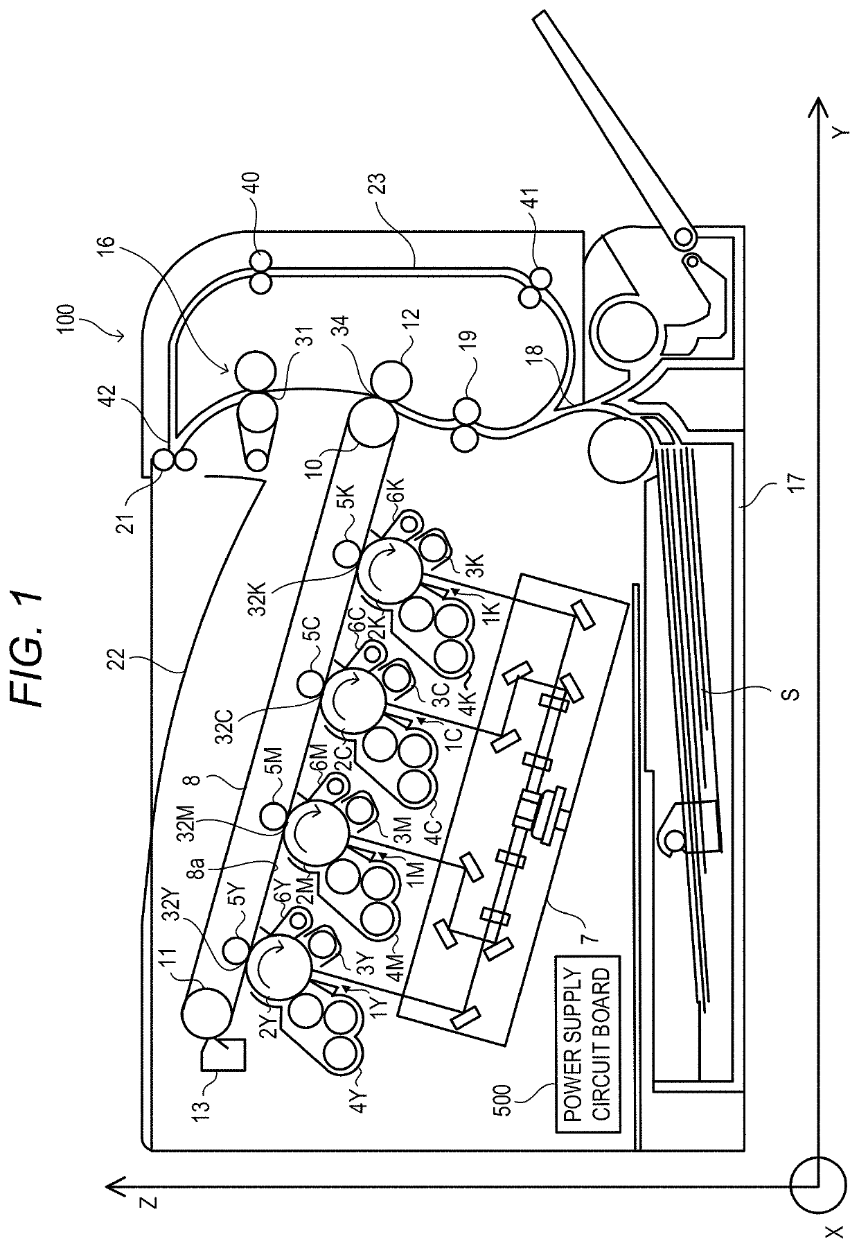
[0024]Now, the first embodiment is described for an image forming apparatus 100 as an example of electric equipment. The image forming apparatus 100 forms an image on a sheet S. FIG. 1 is a sectional view of the image forming apparatus 100. In the following description, a vertical direction from a lower side to an upper side of the image forming apparatus 100 is defined as a Z direction, a horizontal direction from a left side to a right side of the image forming apparatus 100 is defined as a Y direction, and a horizontal direction from a front side to a rear side of the image forming apparatus 100 is defined as an X direction. The image forming apparatus 100 is a full-color printer configured to form a color image on the sheet S with an electrophotographic method. However, the image forming apparatus 100 is not limited to the full-color printer, and may be, for example, an electrophotographic copying machine, a color LED printer, a multifunctional printer (...

second embodiment

[0067]Now, the second embodiment is described with reference to FIG. 6A, FIG. 6B, and FIG. 6C. In the second embodiment, the same structures as those of the first embodiment are denoted by the same reference symbols, and description thereof is herein omitted. The image forming apparatus according to the second embodiment is the same as that of the first embodiment, and hence description thereof is omitted.

[0068](Power Supply Circuit Board of Second Embodiment)

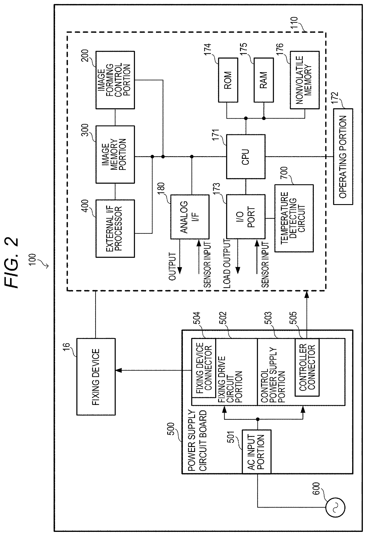
[0069]Now, a power supply circuit board 2500 according to the second embodiment is described with reference to FIG. 6A, FIG. 6B, and FIG. 6C. FIG. 6A, FIG. 6B, and FIG. 6C are sectional views of the power supply circuit board 2500 according to the second embodiment, which is provided in the image forming apparatus 100. The same configurations as those of the reference example, which are illustrated in FIG. 4, are denoted by the same reference symbols, and description thereof is omitted. Electrical connections in the power suppl...


PUM


Abstract

An image forming apparatus including: a circuit board including a varistor, an electric part different from the varistor, and a heatsink for the electric part, the circuit board being supplied with a voltage from a commercial power source; a fan configured to cool the circuit board; and a housing configured to house the circuit board, wherein an opening is formed in the housing, wherein a cross-section shape of the heatsink is a U-shape, the varistor is positioned between a first wall portion and a second wall portion of the heatsink so that the heatsink straddles the varistor, and a position of the heatsink in a direction orthogonal to a longitudinal direction of the heatsink overlaps with a position of the opening in the direction so that an air is caused to flow between the first wall portion and the second wall portion through the opening by the fan.

Description

BACKGROUND OF THE INVENTIONField of the Invention[0001]The present invention relates to an image forming apparatus including a circuit board including a varistor.Description of the Related Art[0002]On a power supply circuit board for, for example, a low-pressure power source for an image forming apparatus, an electric part having a surge absorption characteristic, as represented by a varistor, is provided for the purpose of protecting a circuit on the circuit board from a high voltage current (surge current). In such a rare case that an abnormal voltage is repeatedly applied, the above-mentioned electric part provided for the purpose of surge absorption may gradually be degraded to cause a failure accompanied by scattering of the part. It is extremely rare that the degradation of the electric part progresses to the worst level at which the failure accompanied by the scattering of the part may occur. However, the scattering of the part is required to be assumed. Meanwhile, heat-gener...

Claims


Application Information

Patent Timeline
Patent Type & Authority Patents(United States)
IPC IPC(8): G03G15/00H05K1/00G03G21/20H05K1/02G03G15/20
CPCG03G15/80G03G21/206H05K1/021H05K1/0203G03G15/2017G03G2215/00632
Inventor KUROKI, TOORU
Owner CANON KK
Why Eureka
Try Eureka