Image forming apparatus

a technology forming apparatus, which is applied in the direction of electrographic process apparatus, instruments, optics, etc., can solve the problems of unevenness, increased size of image forming apparatus, and error in measured value, so as to achieve high accuracy and correct unevenness

Inactive Publication Date: 2015-09-22
CANON KK
View PDF19 Cites 0 Cited by
  • Summary
  • Abstract
  • Description
  • Claims
  • Application Information

AI Technical Summary

Benefits of technology

[0012]The present invention may correct an unevenness with high accuracy in a main scanning direction of an image to be formed without increasing the size of an image forming apparatus.

Problems solved by technology

Such image qualities provided by an electrophotography image forming apparatus may be influenced by uneven electrification caused by degradation of a charger which electrostatically charges a photosensitive drum, uneven exposure of a laser scanner, for example, configured to form an electrostatic latent image on a photosensitive drum, uneven development by a developing device which develops an electrostatic latent image or the like.
These unevennesses may cause uneven density and / or uneven color in a main scanning direction (orthogonal to a sheet conveying direction for forming an image on a sheet), which may disadvantageously deteriorate uniformity in a plane.
This may cause an error in measured value because the color value and color density value of the test pattern may change through the two fixing steps.
A special conveying path may be provided to prevent a test pattern from passing through a fixing unit twice, which however may increase the size of the image forming apparatus.

Method used


Image

  • Image forming apparatus
  • Image forming apparatus
  • Image forming apparatus

Examples


first embodiment

Image Forming Apparatus

[0035]According to a first embodiment, an electrophotography laser beam printer is applied. For example, electrophotography is adopted as an image formation method. However, the present invention is applicable to an ink-jet method or a dye sublimation method.

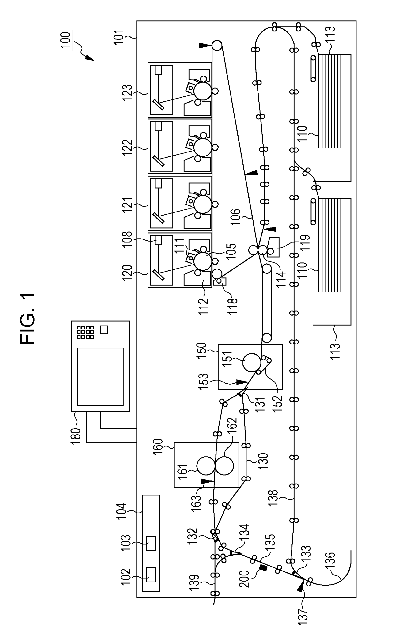
[0036]FIG. 1 is a section view illustrating a structure of an image forming apparatus 100. The image forming apparatus 100 includes a housing 101. The housing 101 contains mechanisms that configure an engine unit and a control board container 104. The control board container 104 contains an engine control unit 102 configured to perform control relating to printing processes (such as a feeding process) by the mechanisms and a printer controller 103.

[0037]As illustrated in FIG. 1, the engine unit includes four YMCK stations 120, 121, 122, and 123. The station 120, 121, 122, and 123 are image forming units configured to transfer toners to a sheet 110 to form an image. Here, YMCK stands for yellow, magenta, cy...

second embodiment

[0141]According to the first embodiment, a measured value from the first test pattern is used to correct a measured value from the second test pattern. On the other hand, according to a second embodiment, a test pattern may be measured only once after a chart is refed, and a conversion table prestored in the storage unit 350 may be used to convert the measured value. The other processing is performed as in the first embodiment.

[0142]FIG. 19 illustrates a conversion table used in the second embodiment. For example, when the color density value measured after a chart is refed (color density value after the second fixing) is equal to 0.454, the color density value is converted to 0.544 that is a color density value after the first fixing. In this manner, the color density value after the second fixing which is measured by the color sensor 200 is converted to a color density value after the first fixing.

[0143]If the color density value measured aster a chart is refed (color density valu...


PUM


Abstract

An image forming apparatus includes an image forming unit configured to form a measurement image on a sheet along a main scanning direction, a fixing unit configured to fix the measurement image onto the sheet, a first calculation unit configured to cause a measuring unit to output a measured value at a predetermined point of measurement on the measurement image, a feeding unit to rotate the sheet 90 degrees and feed the sheet, the sheet to pass through the fixing unit again, and the measuring unit to output measured values at a plurality of points of measurement, and calculate a first correction coefficient from first and second measured values at the point of measurement, a correction unit configured to correct the measured values with the first correction coefficient, and a second calculation unit configured to calculate a second correction coefficient for correcting an unevenness in the main scanning direction.

Description

BACKGROUND OF THE INVENTION[0001]1. Field of the Invention[0002]The present invention relates to an image forming apparatus capable of correcting unevenness of an image in a main scanning direction.[0003]2. Description of the Related Art[0004]An image forming apparatus may provide various image qualities such as grainness, uniformity in a plane, character quality, and reproducibility (including color stability). Such image qualities provided by an electrophotography image forming apparatus may be influenced by uneven electrification caused by degradation of a charger which electrostatically charges a photosensitive drum, uneven exposure of a laser scanner, for example, configured to form an electrostatic latent image on a photosensitive drum, uneven development by a developing device which develops an electrostatic latent image or the like.[0005]These unevennesses may cause uneven density and / or uneven color in a main scanning direction (orthogonal to a sheet conveying direction for...

Claims


Application Information

Patent Timeline
Patent Type & Authority Patents(United States)
IPC IPC(8): G03G15/00
CPCG03G15/5062
Inventor TAKEMURA, TAICHI
Owner CANON KK
Why Eureka
Try Eureka