
Cooling system with supplemental oil extraction from refrigerant

a technology of refrigerant and cooling system, which is applied in the direction of machines/engines, positive displacement liquid engines, light and heating apparatus, etc., to achieve the effect of improving the lifespan of the system

Active Publication Date: 2021-10-12
HEATCRAFT REFRIGERATION PRODS
View PDF8 Cites 0 Cited by
  • Summary
  • Abstract
  • Description
  • Claims
  • Application Information

AI Technical Summary

Benefits of technology

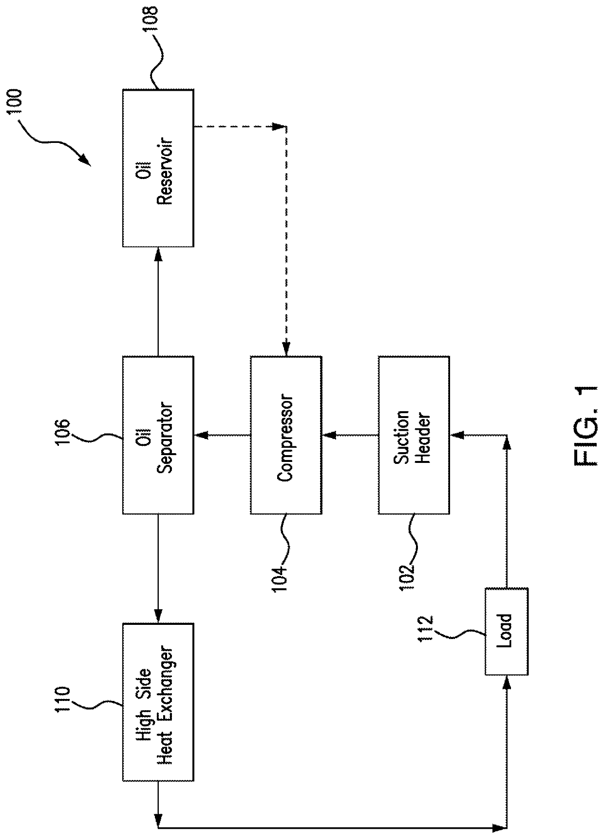
[0003]Refrigeration systems cycle refrigerant to cool spaces, such as residential dwellings, commercial buildings, and / or refrigeration units. A typical commercial refrigeration system includes a suction header, a compressor, an oil separator, and an oil reservoir. Refrigerant enters the compressors through the suction header. The compressors compress refrigerant to concentrate the heat that has been absorbed as spaces have been cooled, making it easier for this heat to be removed from the system. Compressors typically have oiled components. As refrigerant passes through the compressor, the oil on these components mixes with the refrigerant and leaves the compressor and heads to the oil separator. The oil separator receives refrigerant from the compressor and separates most of the oil that may have mixed with the refrigerant in the compressor. By separating the oil from the refrigerant, the oil separator protects other components of the system from being clogged and / or damaged by the oil. The oil separator sends the separated oil to the reservoir so that it may be added back to the compressor as it is needed. However, the oil separator does not remove all the oil from the refrigerant and so some oil reaches the other components of the system. This oil will eventually find its way back to the suction header where it is metered back to the compressor. However, if for some reason the oil is metered back to the compressor faster than the compressor discharges it, damage can result.
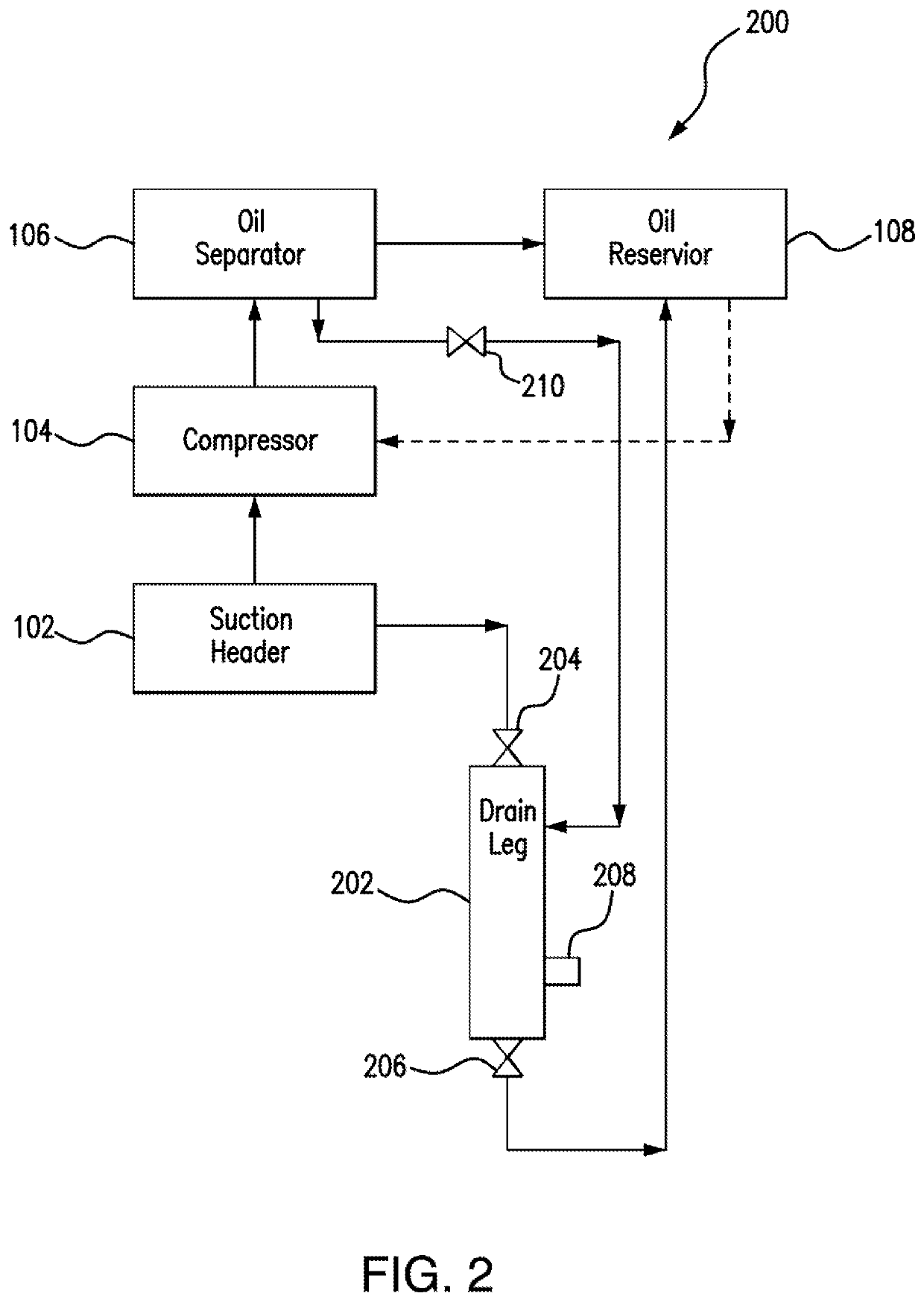
[0004]This disclosure contemplates an unconventional cooling system that includes a drain leg coupled to the suction header. The drain leg uses gravity to separate and collect excess oil from the refrigerant in the suction header. During particular time intervals, the system uses the oil separated from the refrigerant in the oil separator to flush the oil collected in the drain leg to the oil reservoir. As a result, additional oil is removed from the refrigerant, which improves the lifespan of the system. Certain embodiments of the system will be described below.
[0008]Certain embodiments provide one or more technical advantages. For example, certain embodiments include a drain leg that uses gravity to separate and collect excess oil from the refrigerant in the suction header. As a result, additional oil is removed from the refrigerant, which improves the lifespan of the system. Certain embodiments may include none, some, or all of the above technical advantages. One or more other technical advantages may be readily apparent to one skilled in the art from the figures, descriptions, and claims included herein.

Problems solved by technology

However, the oil separator does not remove all the oil from the refrigerant and so some oil reaches the other components of the system.
However, if for some reason the oil is metered back to the compressor faster than the compressor discharges it, damage can result.

Method used


Image

  • Cooling system with supplemental oil extraction from refrigerant
  • Cooling system with supplemental oil extraction from refrigerant
  • Cooling system with supplemental oil extraction from refrigerant

Examples


Embodiment Construction

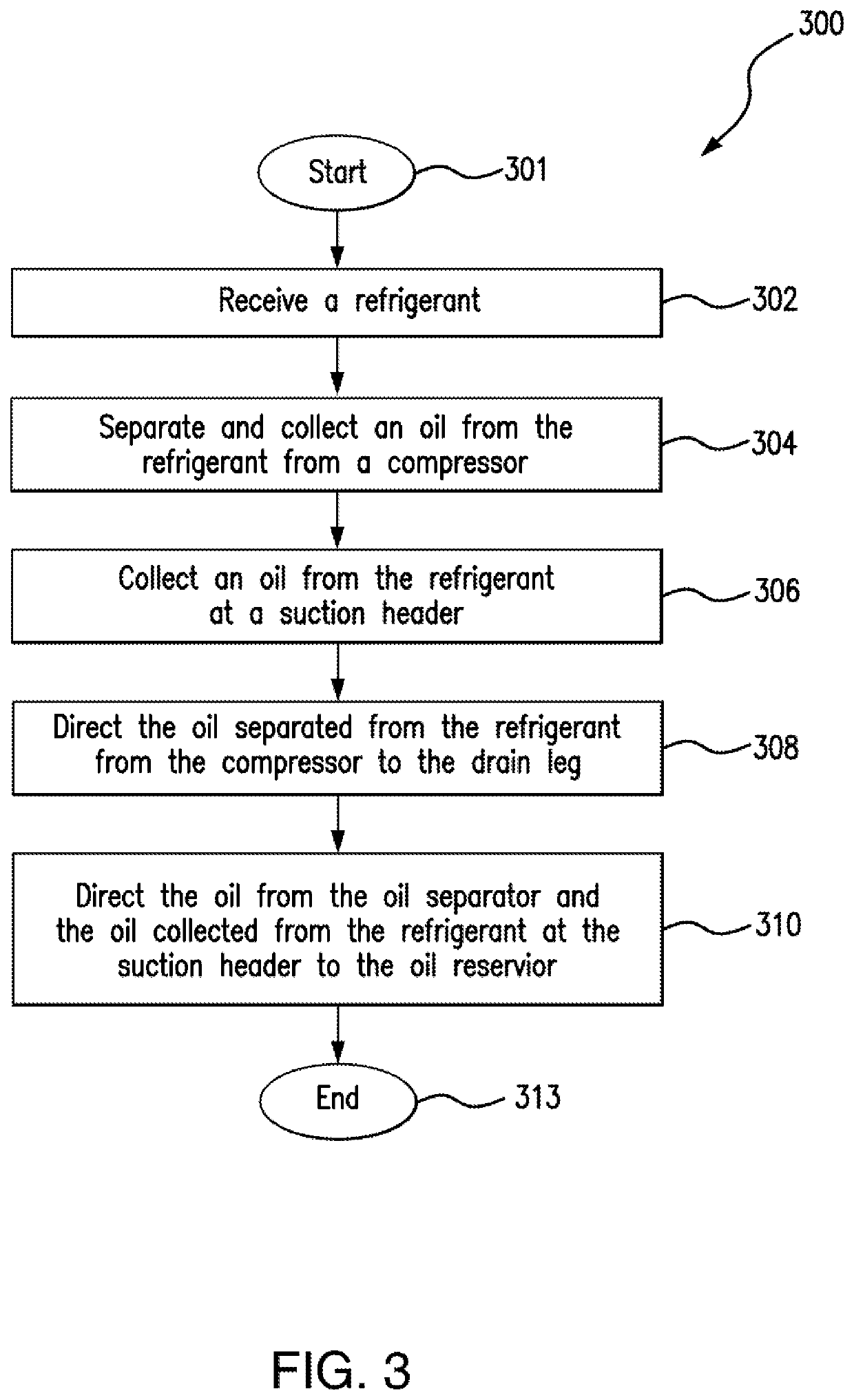
[0013]Embodiments of the present disclosure and its advantages are best understood by referring to FIGS. 1 through 3 of the drawings, like numerals being used for like and corresponding parts of the various drawings.

[0014]A typical commercial refrigeration system includes a suction header, a compressor, an oil separator, and an oil reservoir. Compressors compress refrigerant to concentrate the heat that has been absorbed as spaces have been cooled, making it easier for this heat to be removed from the system. Compressors typically have oiled components. Oil enters the compressor in an uncontrolled manner though the suction header. Oil also enters the compressor in a controlled manner from oil reservoir, as needed. However, a problem occurs when the oil returns to the compressor from the suction header faster than it is used by the compressor. As a result, oil mixes with the refrigerant and is cycled through the other components of the system. This can shorten the lifespan of the sys...


PUM


Abstract

An apparatus includes a suction header, a drain leg, an oil separator, and an oil reservoir. The suction header is configured to receive a refrigerant and the drain leg is coupled to the suction header. The oil separator is configured to separate an oil from the refrigerant from a compressor. During a first mode of operation, the drain leg is configured to collect an oil from the refrigerant from a compressor at the suction header. During a second mode of operation, the oil separator is configured to direct the oil separated from the refrigerant from the compressor through the drain leg and to the oil reservoir.

Description

TECHNICAL FIELD[0001]This disclosure relates generally to a cooling system, such as a refrigeration system.BACKGROUND[0002]Cooling systems are used to cool spaces, such as residential dwellings, commercial buildings, and / or refrigeration units. These systems cycle a refrigerant that is used to cool the spaces.SUMMARY OF THE DISCLOSURE[0003]Refrigeration systems cycle refrigerant to cool spaces, such as residential dwellings, commercial buildings, and / or refrigeration units. A typical commercial refrigeration system includes a suction header, a compressor, an oil separator, and an oil reservoir. Refrigerant enters the compressors through the suction header. The compressors compress refrigerant to concentrate the heat that has been absorbed as spaces have been cooled, making it easier for this heat to be removed from the system. Compressors typically have oiled components. As refrigerant passes through the compressor, the oil on these components mixes with the refrigerant and leaves t...

Claims


Application Information

Patent Timeline
Patent Type & Authority Patents(United States)
IPC IPC(8): F25B43/02F04B39/02F25B31/00F25B41/20
CPCF25B43/02F04B39/0207F04B39/0284F25B31/004F25B41/20F25B2400/071F25B2400/23
Inventor COLE, DOUGLAS
Owner HEATCRAFT REFRIGERATION PRODS
Learn More