Low-frequency ultrasonic atomizing device having large atomization quantity

a technology of atomization device and ultrasonic atomization, which is applied in the direction of spraying apparatus, liquid spraying apparatus, etc., can solve the problems of large atomization amount and uniform droplet siz

Active Publication Date: 2021-11-02
JIANGSU UNIV
View PDF13 Cites 0 Cited by
  • Summary
  • Abstract
  • Description
  • Claims
  • Application Information

AI Technical Summary

Benefits of technology

[0018]High-pressure gas of 3-6 bar enters through the air inlet hole on the end face of the valve body of the gas-liquid valve, the gas passing through the stepped valve core and the laval valve core is accelerated to sonic speed or supersonic speed, the liquid to be atomized flows in through the drainage hole near the outlet of the laval tube and is mixed with sonic gas flow to realize first atomization, and the gas-liquid mixture after the first atomization flows out at high speed along with the high-speed gas flow through the central hole of the end cover of the gas-liquid valve. And flows through the secondary atomization cavity and enters the secondary atomization cavity along the conical gas-liquid inlet, the gas-liquid mixture impacts the end face of the vibrating amplitude transformer to realize secondary atomization, and then droplets subjected to secondary atomization are ejected from the conical gas-liquid inlet again after being repeatedly bounced and atomized in the secondary atomization cavity under the drive of high-speed airflow; and the multiple reflection atomization in the secondary atomization cavity further reduces the droplet diameter of larger droplets in the droplet group, and the droplet diameter is more uniform after multiple atomization, and the atomization amount is obviously improved.The invention has the advantages that:

Problems solved by technology

The disadvantage is that the smaller the amount of atomization, the larger the amount of atomization.
However, the droplet size is not uniform.

Method used


Image

  • Low-frequency ultrasonic atomizing device having large atomization quantity
  • Low-frequency ultrasonic atomizing device having large atomization quantity

Examples


Embodiment Construction

The present invention will be further described below with reference to the drawings and specific embodiments, but the scope of protection of the present invention is not limited thereto.

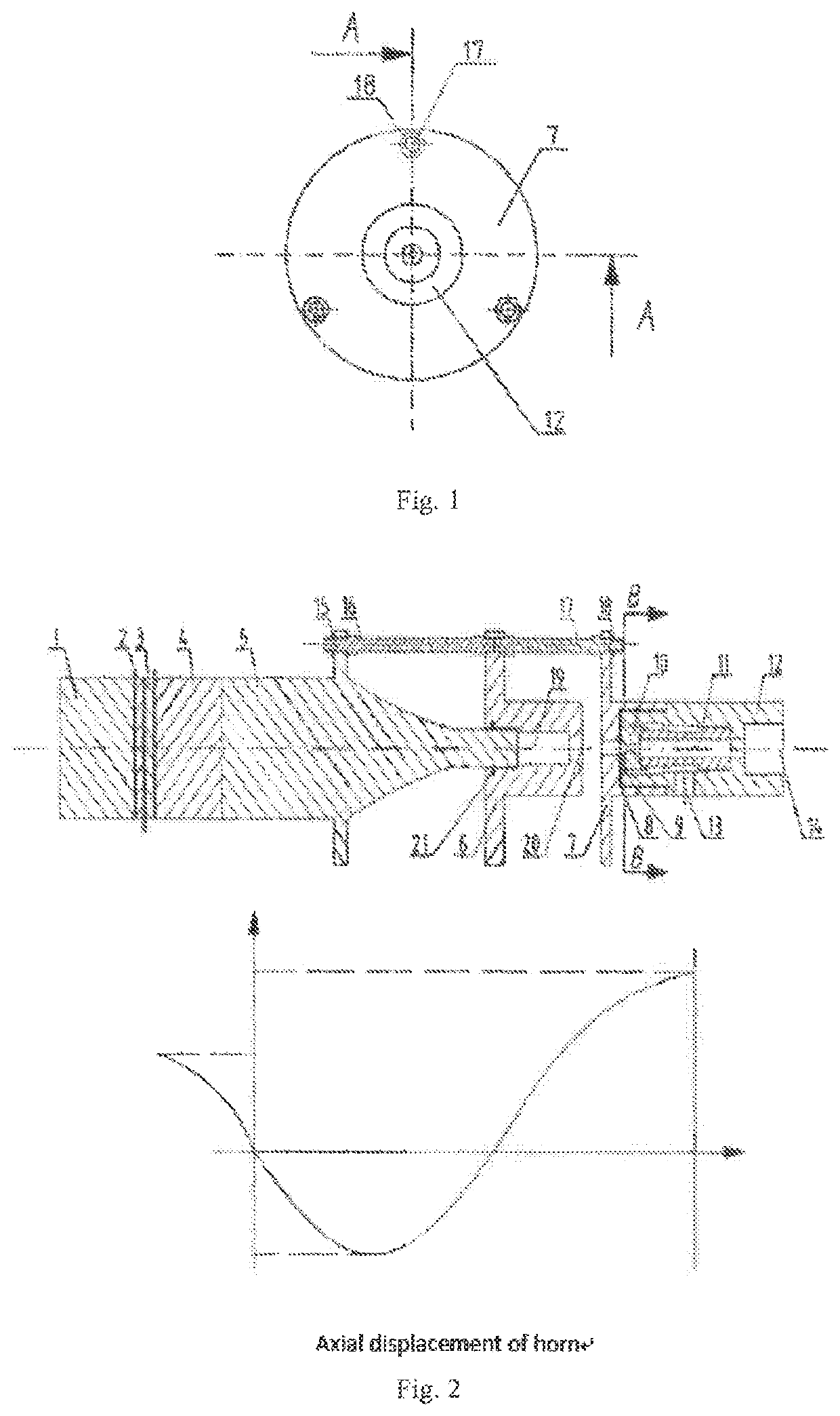
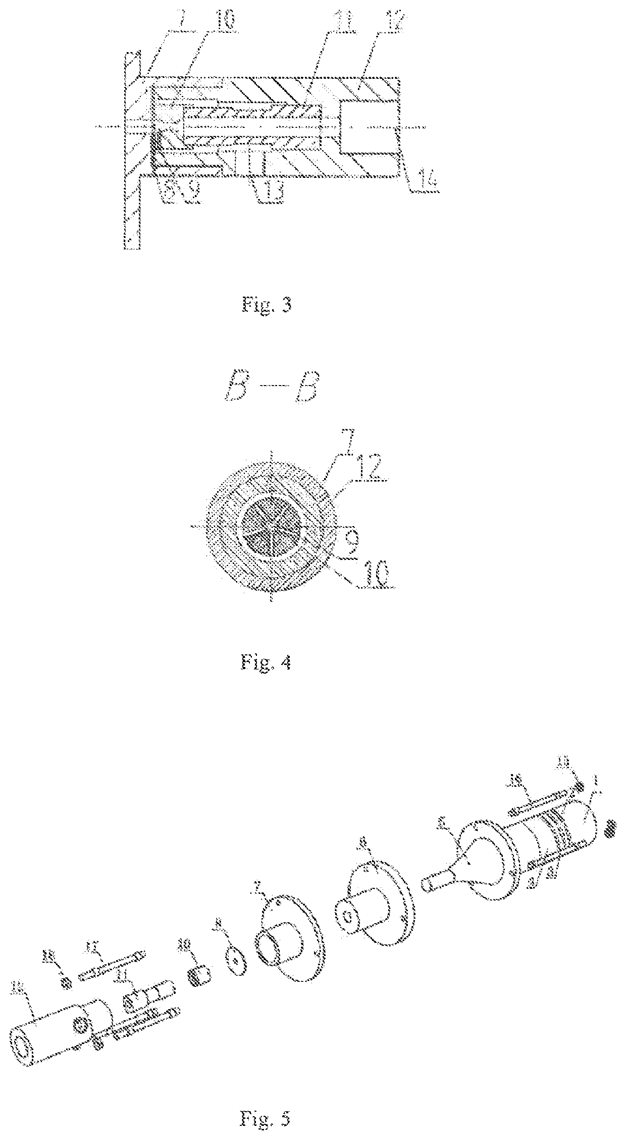
[0027]As shown in figs. 1 and 2, the main body length of the large atomization volume low-frequency ultrasonic atomization device is 110 mm, the length of the ultrasonic atomization nozzle part is 70 mm, the length of the secondary atomization cavity is 15 mm, the distance between the gas-liquid inlet end face of the secondary atomization cavity and the end face of the gas-liquid valve end cover is 3 mm, and the length of the gas-liquid valve body is 28 mm. The low-frequency ultrasonic atomizing device with large atomizing amount comprises a piezoelectric vibrator-3, an amplitude transformer-5, a secondary atomizing cavity-6, a gas-liquid valve end cover-7, a sealing ring-8, a Laval valve core-10, a stepped valve core-11 and a gas-liquid valve body-12. The amplitude transformer-5 is a stepped amplit...


PUM


Abstract

A low-frequency ultrasonic atomizing device includes a piezoelectric vibrator, a horn, a secondary atomizing chamber, a gas-liquid valve end cover, a Laval-type valve core, a stepped valve core, and a gas-liquid valve body. The piezoelectric vibrator is glued onto the horn, and the gas-liquid valve end cap is connected to the gas-liquid valve body by a thread, while both the stepped valve core and the Laval-type valve core are installed within a cylindrical cavity of the valve body, an end of the Laval-type valve core being sleeved at an end of the stepped valve core. The horn and the secondary atomizing chamber, the secondary atomizing chamber and the gas-liquid valve end cover are connected by a double-head stud and a nut. The device achieves multi-stage atomization of droplets, which increases the atomization quantity of a spray device, the droplets being small, and also achieves long distance spraying.

Description

TECHNICAL FIELD[0001]The invention relates to a low-frequency ultrasonic atomization device, belonging to the field of agricultural engineering atomization cultivation.BACKGROUND ART[0002]Ultrasonic atomizers are widely used in agricultural engineering due to their fine and uniform droplet size. At present, in the technical field of ultrasonic atomization, there are mainly two methods to generate power ultrasound: one is to use electroacoustic transducer to generate ultrasound, and the other is to use fluid as power to generate ultrasound. The two methods have their own advantages and disadvantages. The electro-acoustic transducer is used to atomize the droplets produced by the nozzle. The energy consumption is small. The droplet size changes with the design frequency of the piezoelectric vibrator. The higher the frequency, the smaller the droplet size. The disadvantage is that the smaller the amount of atomization, the larger the amount of atomization. However, the droplet size is ...

Claims


Application Information

Patent Timeline
Patent Type & Authority Patents(United States)
IPC IPC(8): B05B17/00B05B17/06B05B7/06
CPCB05B17/0669B05B7/066B05B17/0615B05B17/0607B05B17/0653B05B7/0433B05B7/2424B05B17/0623B05B17/0661
Inventor GAO, JIANMINLIU, XU
Owner JIANGSU UNIV
Why Eureka
Try Eureka