Fuel Injector

a fuel injector and fuel technology, applied in the field of fuel injectors, to achieve the effects of reducing the average droplet diameter of the spray, improving the atomization, and reducing the exhaust emissions

Inactive Publication Date: 2008-02-14
ROBERT BOSCH GMBH
View PDF18 Cites 2 Cited by
  • Summary
  • Abstract
  • Description
  • Claims
  • Application Information

AI Technical Summary

Benefits of technology

[0002]The fuel injector according to the present invention has the advantage that the atomization is improved in a simple manner in that uneven regions or protrusions, which influence the fuel flow, are situated in the flow outlet region. This allows the average droplet diameter of the spray to be reduced without expending additional auxiliary energy, so that lower exhaust emissions are able to be achieved.
[0006]It is very advantageous if the projections are situated in the exit gap because this promotes the generation of a so-called Karmann turbulence path whose periodically detaching vortexes produce turbulence so that the fuel jet disintegrates into smaller droplets than in the related art.
[0007]Moreover, it is advantageous if the projections are positioned downstream from the first flow edge since the fuel jet then already disintegrates into many individual jets at the projections, the fuel jets having a large jet surface.
[0008]Moreover, it is advantageous if the projections have a cylindrical, tetrahedral, pyramidal, conical, prism-shaped, rectangular, semispherical or nub-shaped form since this allows enough turbulence to be generated in the fuel jet exiting the fuel injector to induce the surface of the fuel jet to oscillate, thereby atomizing the fuel jet into very small droplets.
[0009]Furthermore, it is advantageous if the height of the projections increases or decreases downstream in a continuous or stepped manner because the fuel jet is split into many individual jets at the projections, which then collide with other individual jets downstream less often.
[0011]Furthermore, it is advantageous to generate the projections by rasping, micro-embossing, laser removal, etching, micro-electroplating or deposition of a coating since these are suitable methods for creating the projections.

Problems solved by technology

The known fuel injector generates a spray whose average droplet diameter is not small enough for future regulations governing exhaust emissions.

Method used


Image

  • Fuel Injector
  • Fuel Injector
  • Fuel Injector

Examples


Embodiment Construction

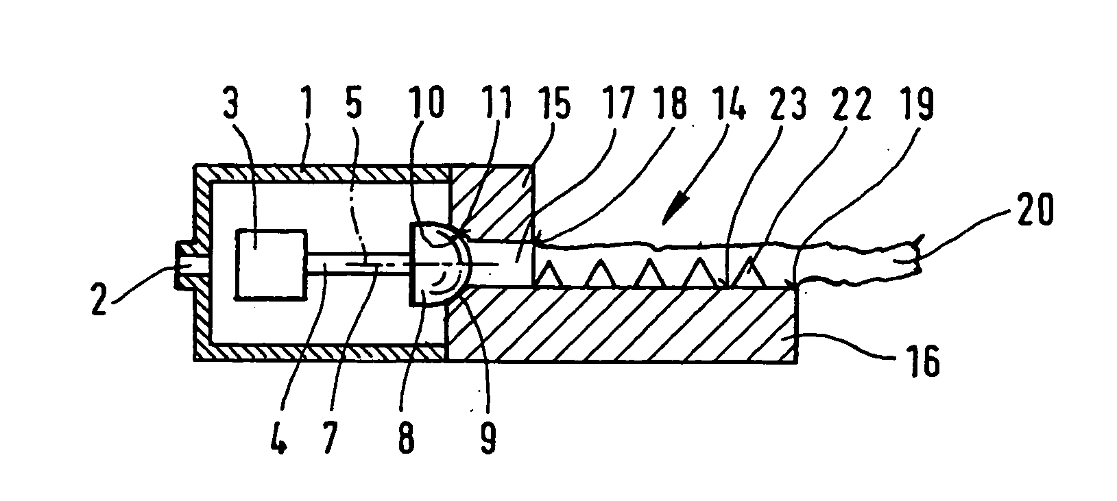
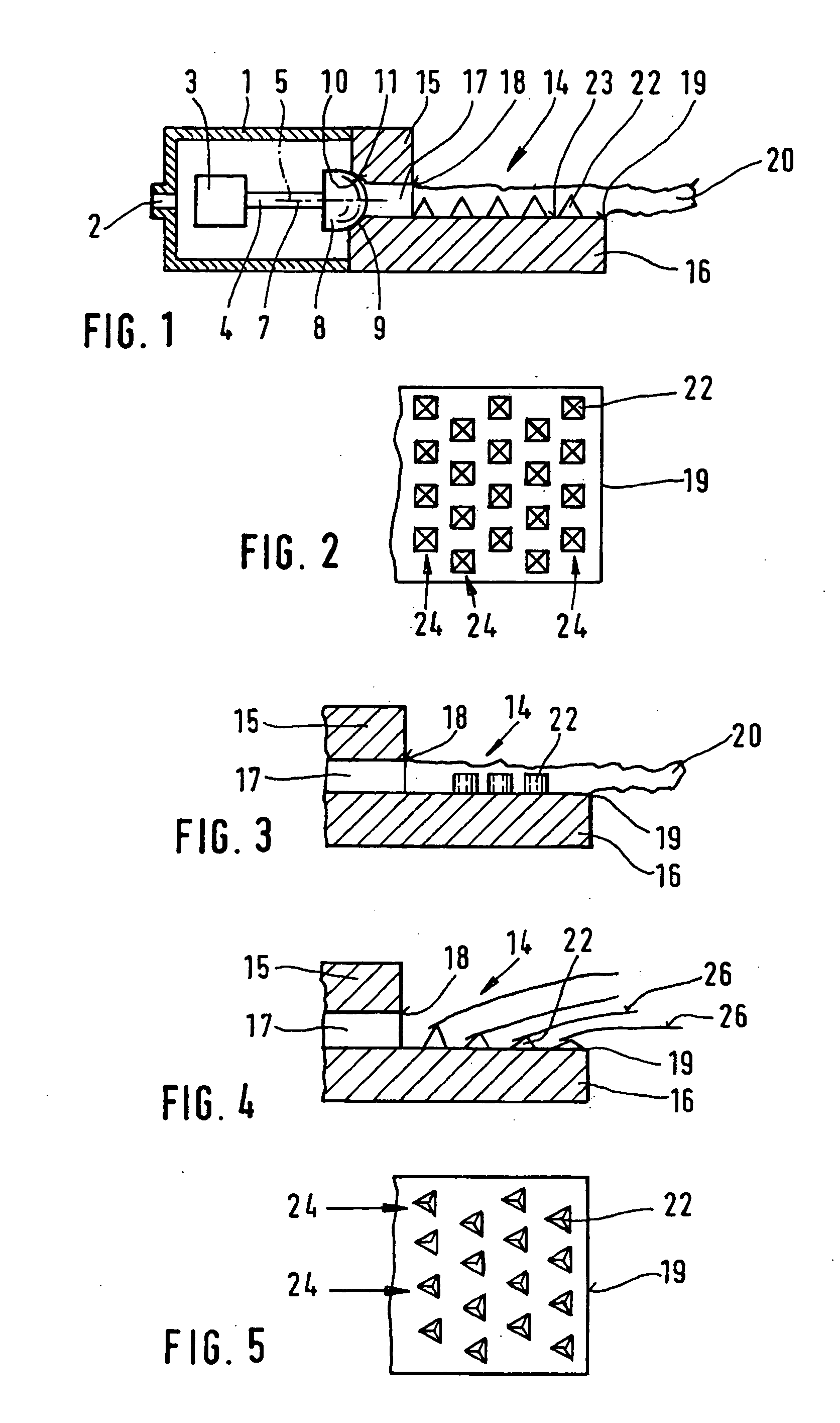
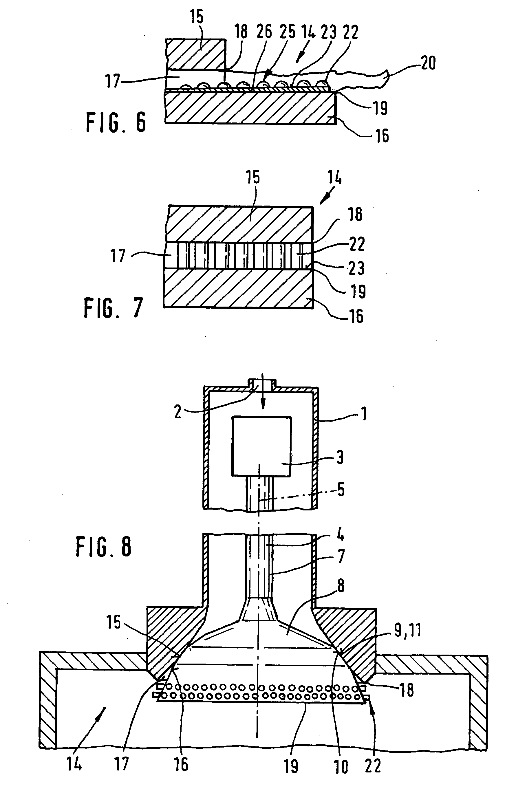
[0021]FIG. 1 shows a simplified view of a first exemplary embodiment of a fuel injector configured according to the present invention.

[0022]The fuel injector is used to finely atomize fuel in the form of spray in order to lower the fuel consumption and exhaust emissions. In the so-called manifold injection, for instance, the fuel is injected into an intake manifold, or in the so-called direct injection it is injected directly into a combustion chamber of the internal combustion engine.

[0023]The fuel injector has a valve housing 1 with an input port 2 for the fuel. Situated in valve housing 1 is a schematically illustrated actuator 3 for the axial adjustment of a valve needle 4. Actuator 3 is, for instance, a magnetic armature which cooperates with an excitable coil, a hydraulic element, a piezoactuator or similar element.

[0024]Valve needle 4 is provided in valve housing 1 so as to be axially displaceable and has, for instance, a needle shaft 7 facing actuator 3 and a valve-closure m...


PUM


Abstract

Known fuel injectors have a valve-closure member, which cooperates with a sealing seat of a valve seat, and a flow exit region situated downstream from the sealing seat, the fuel spray generated by the fuel injectors having an average droplet diameter that is not small enough for future regulations governing exhaust emission. In the fuel injector according to the present invention the atomization is improved in a simple manner and the average droplet diameter is reduced without additional auxiliary power. The projections which influence the fuel flow are situated in the flow exit region.

Description

BACKGROUND INFORMATION [0001]U.S. Pat. No. 4,759,335 describes a fuel injector, which has a valve-closure member cooperating with a sealing seat of a valve seat, and a flow outlet region downstream from the sealing seat. The known fuel injector generates a spray whose average droplet diameter is not small enough for future regulations governing exhaust emissions.SUMMARY OF THE INVENTION [0002]The fuel injector according to the present invention has the advantage that the atomization is improved in a simple manner in that uneven regions or protrusions, which influence the fuel flow, are situated in the flow outlet region. This allows the average droplet diameter of the spray to be reduced without expending additional auxiliary energy, so that lower exhaust emissions are able to be achieved.[0003]It is especially advantageous if the flow outlet region is formed by a first wall and a second wall which is situated opposite the first wall, an exit gap being formed between the first wall ...

Claims


Application Information

Patent Timeline
Patent Type & Authority Applications(United States)
IPC IPC(8): F02M29/04F02M61/16F02M61/18
CPCF02M61/162F02M61/188F02M61/18F02M61/168
Inventor ARNDT, STEFANMAIER, MARTINHEYSE, JOERG
Owner ROBERT BOSCH GMBH
Why Eureka
Try Eureka