Control device of high-pressure fuel pump of internal combustion engine

a technology of high-pressure fuel pump and control device, which is applied in the direction of electric control, positive displacement liquid engine, machines/engines, etc., can solve the problems of worsening emission gas, and achieve the effect of reducing the risk of fuel pressure rising and improving the safety of the system

Inactive Publication Date: 2006-07-06
HITACHI ASTEMO LTD
View PDF5 Cites 43 Cited by
  • Summary
  • Abstract
  • Description
  • Claims
  • Application Information

AI Technical Summary

Benefits of technology

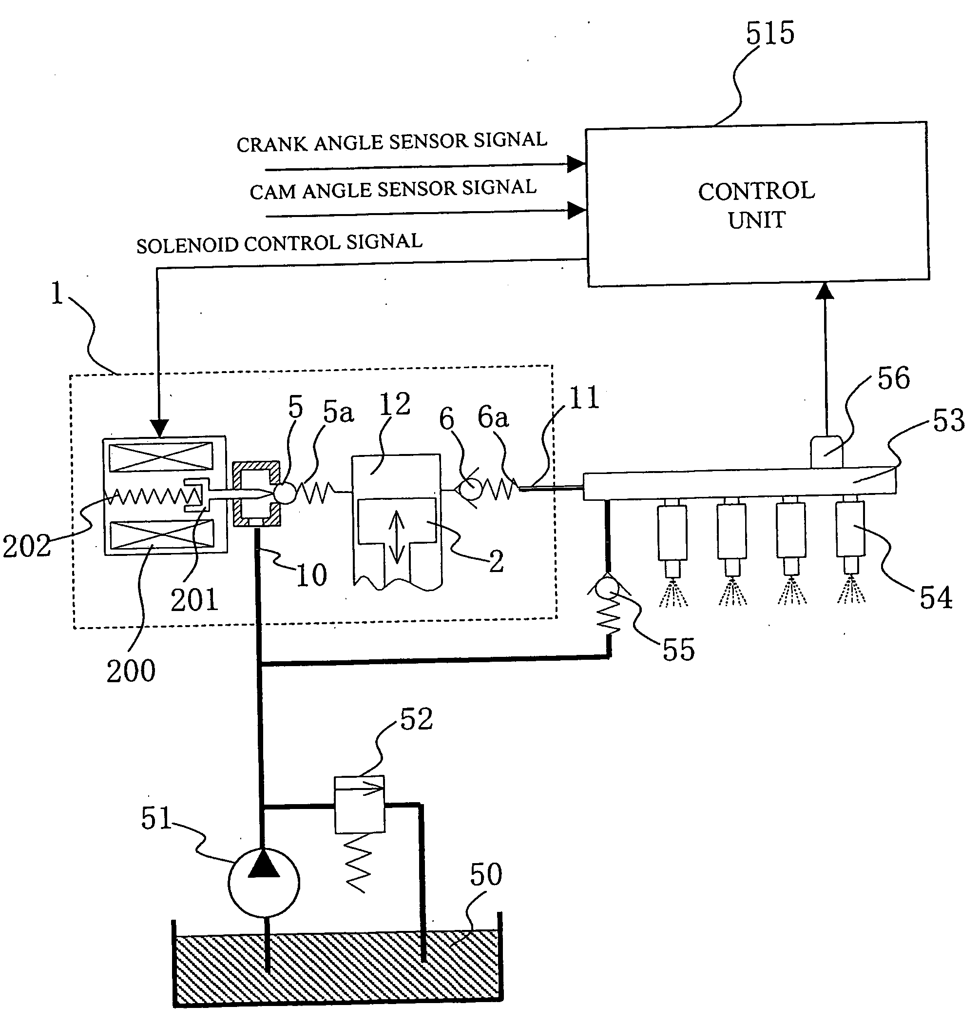
[0034] In the control device of a high-pressure fuel pump of an internal combustion engine according to the present invention constructed as described above, when a pressure difference between the target fuel pressure and the measured fuel pressure is under a fixed value, ordinary F/B control is performed so as to cause the measured fuel pressure to follow the target fuel pressure; and when the target fuel pressure is higher than the measured fuel pressure, entire discharge control from the bottom dead center of the plunger can be performed. In other words, the high-pressure fuel pump is caused to perform the entire discharge, whereby the measured fuel pressure can be brought close to the target fuel pressure swiftly.
[0035] On the other hand, when the me

Problems solved by technology

As understood from these examples, the conventional one will become unable to realize the optimum fuel pressure in an operating condition of the internal combustio

Method used


Image

  • Control device of high-pressure fuel pump of internal combustion engine
  • Control device of high-pressure fuel pump of internal combustion engine
  • Control device of high-pressure fuel pump of internal combustion engine

Examples


third embodiment

[0105]FIG. 17 is a control block diagram showing the present invention concerning processing by the pump control signal calculating means 1502. The pump control signal calculating means 1502 top- and -bottom limits, on calculating a reference angle REFANG, a phase operated by the reference angle operating means 704 by phase limiting means 1101, and regards this as a reference angle REFANG. In this respect, the phase limiting means 1101 can be applied to pump control having a variable capacity mechanism by phase control.

[0106]FIG. 18 is a flow chart showing control of the high-pressure fuel pump 1 by the control device of the high-pressure fuel pump. In a step 1001, the interruption processing synchronized to time like, for example, every 10 ms is performed. In this respect, for the interruption processing, a processing synchronized to rotation like every the crank angle of 180 deg may be used.

[0107] In a step 1002, the phase is operated by the reference angle operating means 704; i...

fourth embodiment

[0114] Also, although the pump control signal calculating means 1502 according to the above-described embodiment has calculated the reference angle REFANG by limiting a phase obtained by calculating by the reference angle operating means 704, by the phase limiting means 1101, the present invention is not limited thereto, but as in the case of the fourth embodiment shown in, for example, FIG. 20, it may be possible to finally limit the output commencement angle STANG obtained by calculating by the phase limiting means 1301 by taking account of correction in the solenoid working delay correction means 705 to the reference angle REFANG of the reference angle operating means 704.

[0115] Further, as shown in the fifth embodiment of FIG. 21, it is also possible to limit an amount of F / B control of the reference angle operating means 704 by the F / B limiting means 1401 into the reference angle REFANG, and as shown in the sixth embodiment of FIG. 22, it may be possible to limit the amount of ...


PUM


Abstract

A control device of a high-pressure fuel pump of an internal combustion engine capable of improving stability in controlling the drive of the high-pressure fuel pump by limiting the end timing of a drive signal of the high-pressure fuel pump and driving an actuator in a control effective range of the high-pressure fuel pump. The control device of the high-pressure fuel pump of the internal combustion engine has a fuel injection valve provided on a cylinder and the high-pressure fuel pump for pumping fuel to the fuel injection valve, wherein the high-pressure fuel pump comprises a pressure chamber, a plunger for pressurizing the fuel in the pressure chamber, a fuel valve provided in the pressure chamber, and the actuator for operating the fuel valve. The control device has means for calculating the drive signal of the actuator so as to realize the variable discharge of the high-pressure fuel pump. The means for calculating the drive signal has means for limiting the end timing of the drive signal of the actuator to a predetermined phase and/or means for limiting the output timing of the drive signal of the actuator to be within a predetermined phase range.

Description

TECHNICAL FIELD [0001] The present invention relates to a control device of a high-pressure fuel pump of an internal combustion engine, and more particularly to a control device of a high-pressure fuel pump of an internal combustion engine capable of realizing the variable discharge of high-pressure fuel to be pumped to a fuel injection valve of the internal combustion engine. BACKGROUND ART [0002] The present automobiles have been required to reduce emission gas of specific substances such as carbon monoxide (CO), carbon hydride (HC) and oxide nitrogen (NOx) which are contained in emission gas from automobiles from a point of view of environmental preservation, and with the objective of these reduction, a direct injection engine (direct injection internal combustion engine) has been developed. In the direct injection internal combustion engine, fuel injection using a fuel injection valve is directly performed within a combustion chamber of a cylinder, and a particle size of fuel to...

Claims


Application Information

Patent Timeline
IPC IPC(8): F04B49/00F02D41/30F02D41/38F02M59/20F02M59/36F02M63/02F04B49/24
CPCF02D41/3845F02D2041/2027F02D2200/0602F02D2200/503F02M59/20F02M59/366F02M63/0225F04B49/243F02D41/1401F02D2250/31
Inventor OKAMOTO, TAKASHIYAMADA, HIROYUKISHIMADA, KOUSAKUMATSUFUJI, KOJI
Owner HITACHI ASTEMO LTD
Why Eureka
Try Eureka