
A Combined Stirring Paddle for Improving Suction Capability and Mixing Efficiency

A technology of mixing efficiency and suction capacity, applied in the field of combined stirring paddles, which can solve problems such as unfavorable mixing, emulsification, and excessive stirring

Active Publication Date: 2019-12-03
CHONGQING UNIV
View PDF4 Cites 0 Cited by
  • Summary
  • Abstract
  • Description
  • Claims
  • Application Information

AI Technical Summary

Problems solved by technology

During the stirring process, the traditional rigid stirring impeller tends to form a large wake behind the blade, making it difficult for the energy to be transmitted to the edge of the stirring tank, and the isolation area cannot be effectively reduced. The energy utilization rate is low and the mixing effect is low. poor
In the process of industrial production, the method of increasing the rotating speed is usually used to improve the mixing effect. In the process of liquid-liquid mixing, excessive rotating speed will easily cause excessive stirring, entrapment of air, and emulsification phenomenon, which is not conducive to mixing

Method used


Image

  • A Combined Stirring Paddle for Improving Suction Capability and Mixing Efficiency
  • A Combined Stirring Paddle for Improving Suction Capability and Mixing Efficiency
  • A Combined Stirring Paddle for Improving Suction Capability and Mixing Efficiency

Examples


Embodiment 1

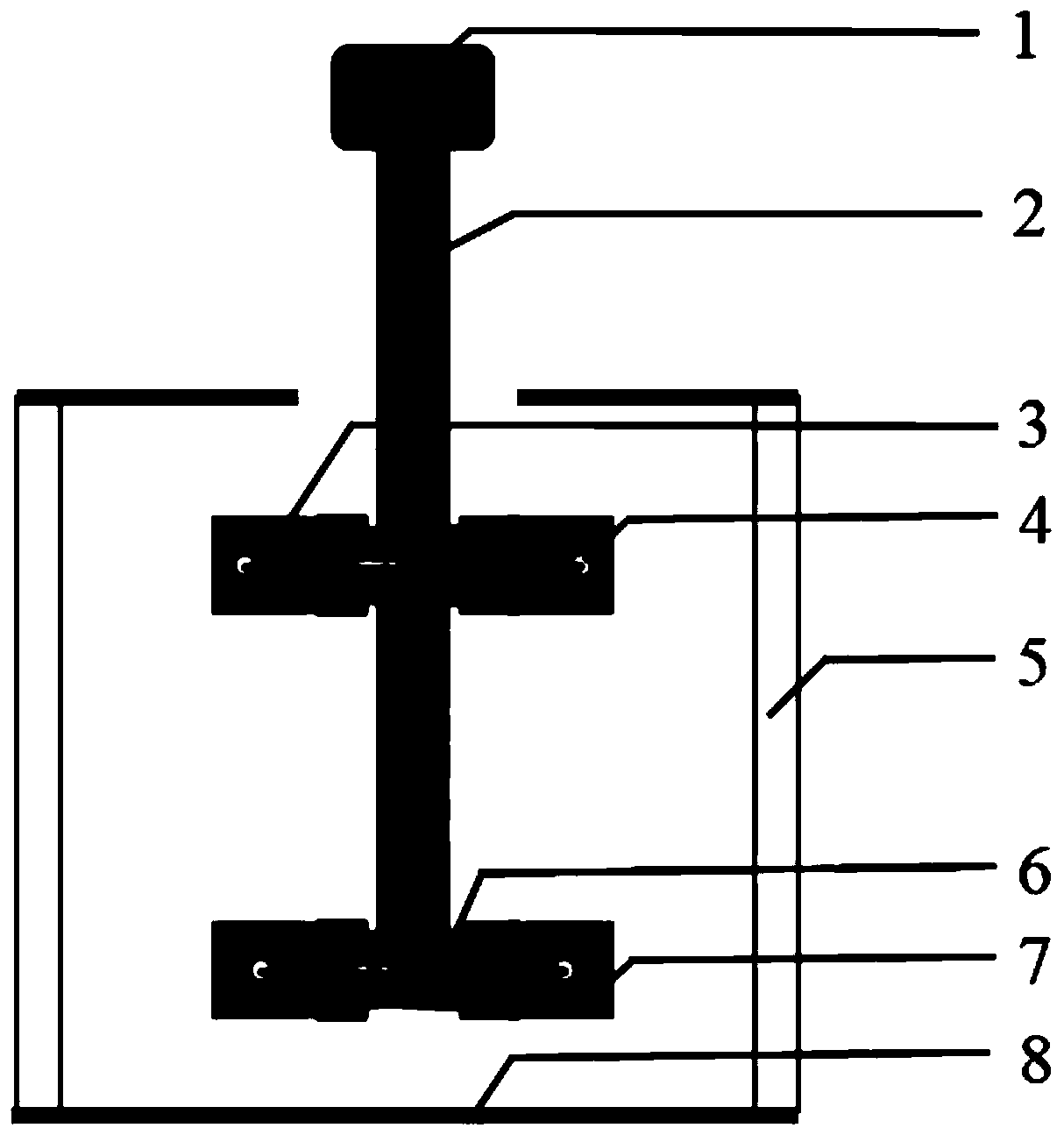
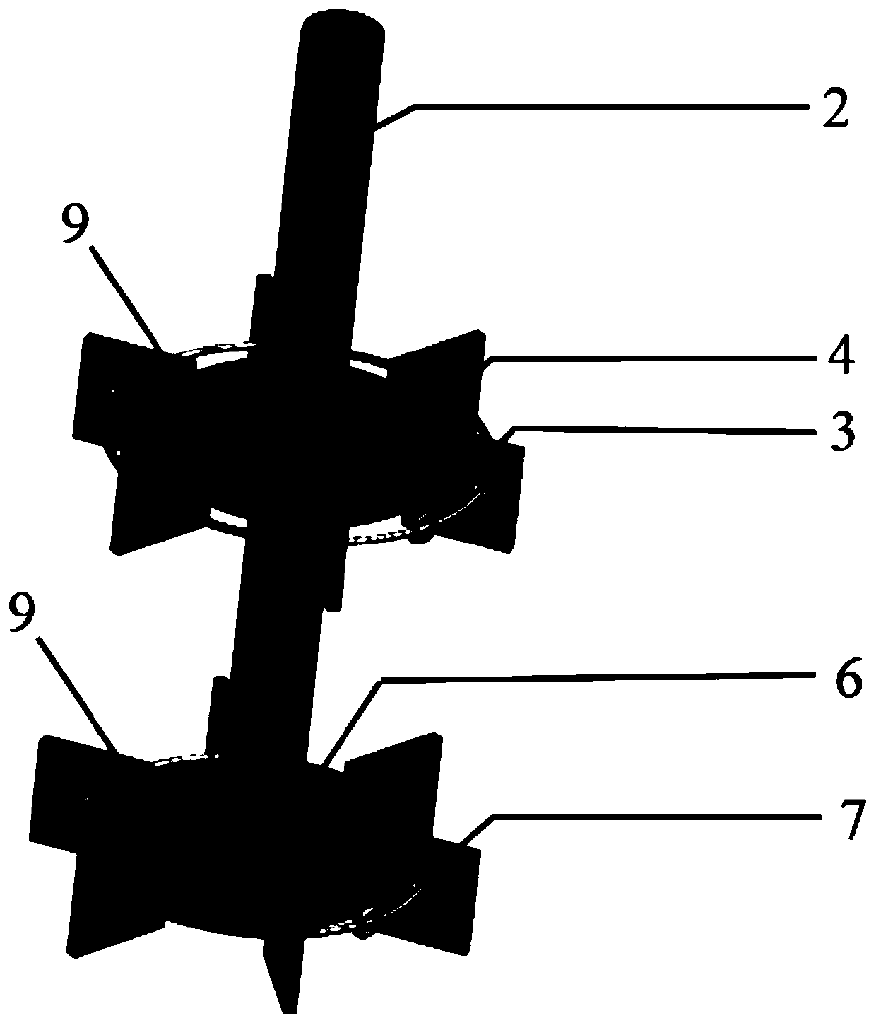
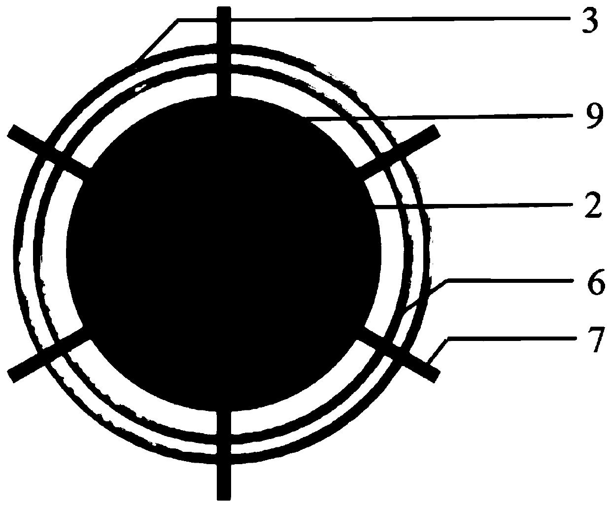
[0025] A combined stirring paddle that improves suction capacity and mixing efficiency is characterized in that: it mainly includes a stirring shaft 2, and at least two disc bodies 9, flexible ropes 6 having the same number as the disc bodies 9, several rigid Paddle 7.

[0026] The stirring shaft 2 is a circular shaft, one end of which is connected to power, and the other end is located in the stirring tank 8 .

[0027] Each disc body 9 is fixed on the stirring shaft 2 . The stirring shaft 2 penetrates the central hole of each disc body 9 .

[0028] Each disc body 9 is fixed with several rigid paddles 7 . These rigid paddles 7 are inserted around the disc body 9 and surround the stirring shaft 2 radially.

[0029] Each rigid paddle 7 has a circular through hole 4 .

[0030] Each disc body 9 is configured with a flexible rope 6 . After a flexible rope 6 passes through each circular through hole 4 on all the rigid paddles 7 around a disc body 9 in turn, the two ends of the ...

Embodiment 2

[0033] The main structure of this embodiment is the same as that of Embodiment 1, and further, the two nodes on the stirring shaft 2 are respectively marked as node I and node II. Node I is close to the end of the stirring shaft 2 connected to the motor 1, and node II is close to the lower end of the stirring shaft 2.

[0034] The two disc bodies 9 are respectively denoted as disc body I and disc body II. Disc body I and disc body II are respectively fixed at node I and node II. That is, the stirring shaft 2 has two layers of combined stirring paddles up and down.

[0035] The number of blades of the rigid paddles 7 connected by the disc body I and the disc body II is equal. The number of blades of the rigid stirring paddle 7 is at least three.

Embodiment 3

[0037] The main structure of this embodiment is the same as embodiment 1 or 2, further:

[0038] The blade length of the rigid paddle 7 is L. The end of the rigid paddle 7 away from the stirring shaft 2 is the tip, and the distance between the circular through hole 3 and the tip of the rigid paddle 7 is a. a<2 / 3L. The circular through-holes 4 on each blade are located at the same position


PUM


Abstract

The purpose of the present invention is to provide a combined paddle that improves suction capacity and mixing efficiency, mainly including a stirring shaft, and at least two disc bodies, flexible ropes with the same number as the disc bodies, and several rigid paddles . The motor drives the rigid-flexible combined stirring paddle to rotate in the stirring tank, and transfers energy to the fluid in the stirring tank, so as to obtain a suitable flow field. During the stirring process, the rigid-flexible combined stirring paddle of the present invention can improve the mixing effect of the material and the suction capacity of the paddle, and reduce the isolation zone, enhanced fluid mixing. Compared with the prior art, the present invention can reliably improve the fluid mixing efficiency, and achieve better mixing effect at a lower rotating speed.

Description

technical field [0001] The invention relates to a stirring device in the production process of chemical industry, hydrometallurgy, pharmacy, food, etc., and specifically refers to a combined stirring paddle composed of rigid blades and flexible ropes. Background technique [0002] Stirring reactors are widely used in chemical, hydrometallurgy, pharmaceutical, food and other process industries. It inputs mechanical energy to the fluid in the stirring tank through the mechanical rotation of the stirring paddle, and realizes heat and mass transfer through the shearing action of the paddle. Therefore, a suitable flow field is formed in the stirring tank, and the fluid mixing is strengthened. [0003] The study found that there are two different types of mixing areas in stirred reactors: chaotic mixing area and isolation area. Enlarging the chaotic mixing area and reducing the isolation area are important to improve the fluid mixing efficiency and reduce the energy consumption of...

Claims


Application Information

Patent Timeline
Patent Type & Authority Patents(China)
IPC IPC(8): B01J19/18B01F7/18
CPCB01J19/0066B01J19/18B01F27/053B01F27/074B01F27/1125B01F27/17B01F27/191B01F27/90
Inventor 刘作华许传林陶长元谷德银邱发成杜军范兴刘仁龙谢昭明吴丙山孔令峰唐金晶李兵许恢琴杨义张柱王靓熊黠王闯周小霞唐小骅黄诗雨刘青松
Owner CHONGQING UNIV
Learn More