Flywheel and paddle assembly for a chipping or shredding apparatus, and an apparatus incorporating same

a technology of flywheel and paddle, which is applied in the field of disk-type chipper or shredder, can solve the problems of sub-optimal material particle discharge performance, speed of paddle rotation is slower than optimal, and the rotational speed of the flywheel is faster than optimal

Active Publication Date: 2021-11-16
WOODLAND MILLS INC
View PDF32 Cites 6 Cited by
  • Summary
  • Abstract
  • Description
  • Claims
  • Application Information

AI Technical Summary

Problems solved by technology

A problem with prior art chipping and shredding apparatuses is that when they are configured to rotate the flywheel at a speed that is optimized for chipping or shredding material, the resulting speed of the rotation of the paddle is slower than optimal, resulting in sub optimal material particle discharge performance.
On the other hand, when they are configured to rotate the paddle at a speed that is optimized for discharging material particles from the housing, the resulting rotational speed of the flywheel is faster than optimal, resulting in suboptimal chipping or shredding performance.

Method used


Image

  • Flywheel and paddle assembly for a chipping or shredding apparatus, and an apparatus incorporating same
  • Flywheel and paddle assembly for a chipping or shredding apparatus, and an apparatus incorporating same
  • Flywheel and paddle assembly for a chipping or shredding apparatus, and an apparatus incorporating same

Examples


Embodiment Construction

[0048]The present invention is described in more detail with reference to exemplary embodiments thereof as shown in the appended drawing. While the present invention is described below including preferred embodiments, it should be understood that the present invention is not limited thereto. Those of ordinary skill in the art having access to the teachings herein will recognize additional implementations, modifications, and embodiments which are within the scope of the present invention as disclosed and claimed herein.

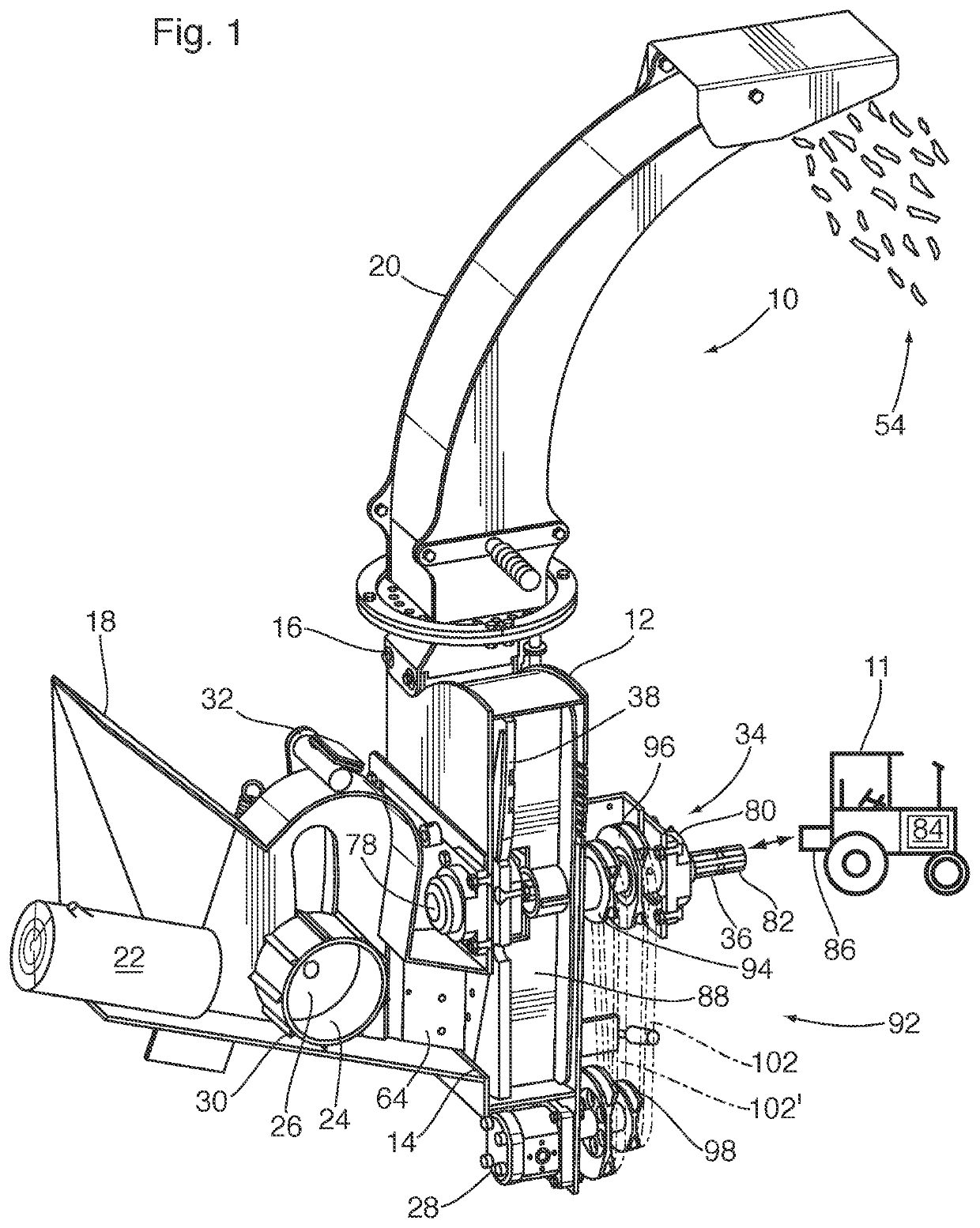
[0049]A chipping or shredding apparatus 10 according to an embodiment of the present invention is shown in FIG. 1. For the purposes of illustration only, the apparatus 10 is shown in the form of a wood chipper configured for removably mounting on a tractor 11 outfitted with a power take off (PTO). However, the present invention is not limited to wood chippers, and is instead broadly directed to other apparatuses which are configured to reduce organic and inorganic mate...


PUM


Abstract

A flywheel and paddle assembly for a chipping or shredding apparatus, including a wood chipper, a brush chipper, and a leaf shredder. The assembly has a flywheel attached coaxially to a drive shaft. The flywheel has at least one aperture extending from the front side to the back side, and carries at least one knife adjacent to the at least one aperture. The knife presents a knife edge on the front side of the flywheel. A paddle is rotatably mounted coaxially to the drive shaft adjacent to the back side of the flywheel. The paddle is configured to rotate on the drive shaft independently of the flywheel. A chipping or shredding apparatus incorporating the aforesaid flywheel and paddle assembly is also disclosed.

Description

FIELD OF THE INVENTION[0001]The present invention relates to the field of chipping or shredding apparatuses. More particularly, the present invention relates to disk type chippers or shredders wherein one or more cutting knives are carried rotatably on the face of a rotating disk-shaped flywheel.BACKGROUND OF THE INVENTION[0002]Many industrial, commercial, and household applications require the breaking up of relatively large objects into smaller pieces. The reduction process is variously referred to as cutting, chipping, shredding, mulching, or grinding, depending in part on the size of the end product.[0003]It is known to accomplish such a reduction process with a chipping or shredding apparatus of the type having knives mounted directly onto a rotating disk, or flywheel. The flywheel is typically a relatively heavy, steel disk mounted in a housing. The flywheel has slots or apertures where the knives are mounted. The known apparatuses are typically configured to allow lawn and ga...

Claims


Application Information

Patent Timeline
Patent Type & Authority Patents(United States)
IPC IPC(8): B02C18/24B27L11/00B27L11/02B02C18/22
CPCB02C18/24B02C18/2216B02C18/2283B27L11/002B27L11/02B02C18/22B02C18/143B02C2201/066A01G3/002
Inventor BRAMLEY, NEIL K.MALCOLM, JOSHUA J.
Owner WOODLAND MILLS INC
Why Eureka
Try Eureka