
Communication device, communication system, and communication method

a communication system and communication device technology, applied in the direction of electrical equipment, particular environment based services, vehicle components, etc., can solve the problems of erroneous communication, erroneous connection, and large electrical components, and achieve the effect of stabilizing communication and suppressing erroneous communication

Active Publication Date: 2021-11-16
SONY SEMICON SOLUTIONS CORP
View PDF14 Cites 0 Cited by
  • Summary
  • Abstract
  • Description
  • Claims
  • Application Information

AI Technical Summary

Benefits of technology

[0006]In a communication system using an electric field communication technology, communication performance varies depending on an electrode size of an antenna. An increase in the electrode size increases a communicable range but may cause erroneous communication (erroneous connection) that is not intended by a user.
[0007]It is desirable to provide a communication device, a communication system, and a communication method that make it possible to suppress erroneous communication and stabilize communication.
[0012]The effective electrode area of at least one of the first electrode or the second electrode is changed on the basis of at least one of the operations of the communication circuit, the type of transmission data, or the communication stages. Hence, the communication device, the communication system, or the communication method according to the embodiment of the present disclosure makes it possible to suppress erroneous communication and stabilize communication.
[0013]It is to be noted that the effect described herein is not necessarily limitative and any effect described in the present disclosure may be achieved.

Problems solved by technology

An increase in the electrode size increases a communicable range but may cause erroneous communication (erroneous connection) that is not intended by a user.

Method used


Image

  • Communication device, communication system, and communication method
  • Communication device, communication system, and communication method
  • Communication device, communication system, and communication method

Examples


first embodiment

1. FIRST EMBODIMENT

[1.1 Configuration]

(Overall Configuration of Communication Device)

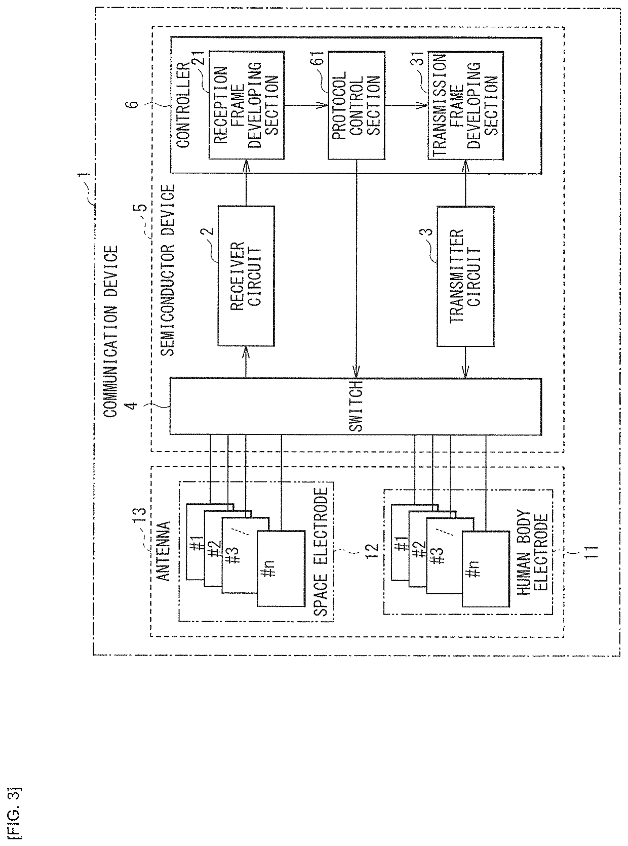
[0068]FIG. 3 schematically illustrates a configuration example of a communication device 1 according to a first embodiment of the present disclosure.

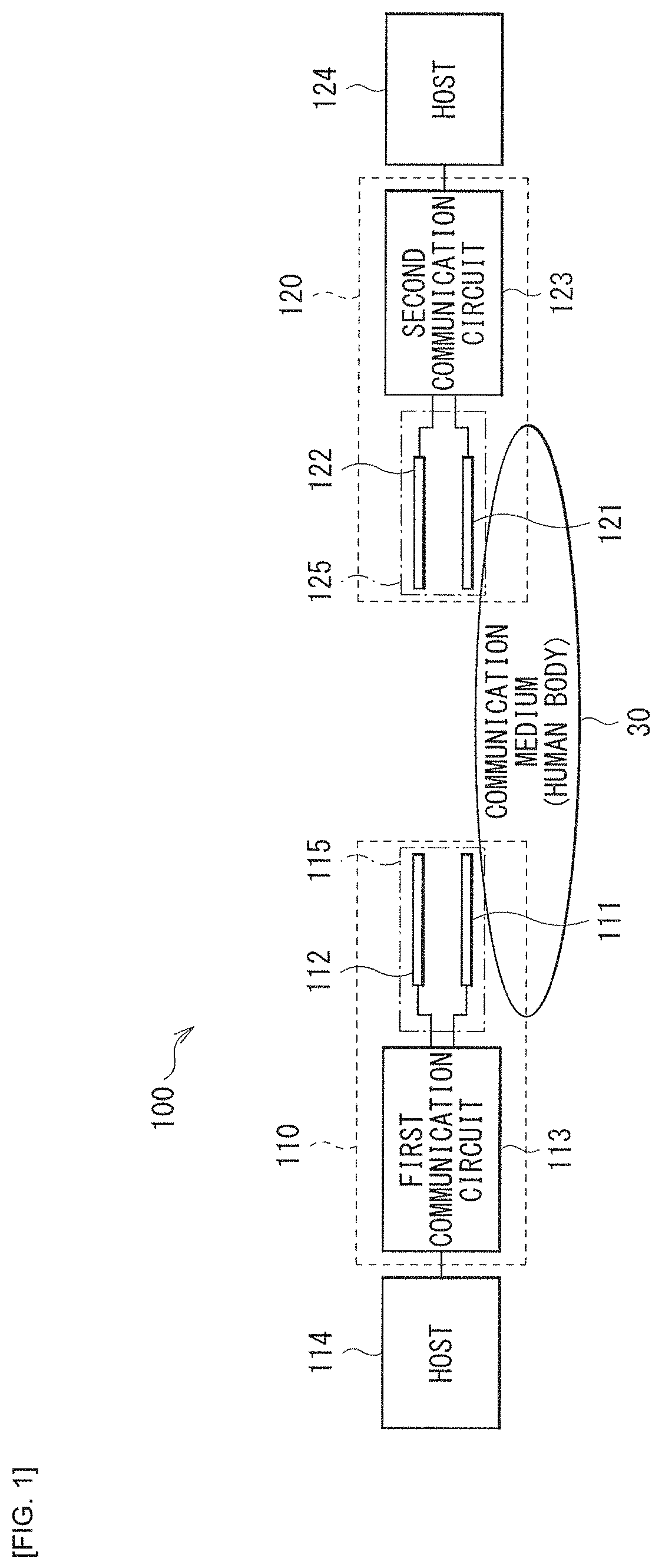
[0069]The communication device 1 according to the present embodiment may be used as at least one of the first communication device 110 or the second communication device 120 of the communication system 100 according to the above-described comparative example. In this case, the first communication device 110 and the second communication device 120 may each be a transmitter / receiver that bidirectionally transmit and receive data. For example, a device to be communicated with by the communication device 1 according to the present embodiment may be the first communication device 110, while the communication device 1 according to the present embodiment is the second communication device 120.

[0070]An example of standards for standardization of a communication...

second embodiment

2. SECOND EMBODIMENT

[0112]Next, a communication device and a communication system according to a second embodiment of the present disclosure will be described. It is to be noted that like reference numerals are used hereinbelow to refer to portions substantially the same as components of the communication device and the communication system according to the first embodiment and the explanations are omitted as necessary.

[2.1 Configuration and Operation]

[0113]A configuration of the communication device 1 according to the present embodiment may be substantially similar to the configuration of FIG. 3. In addition, an electrode structure of the antenna 13 may be any one of the electrode structures of FIG. 4 to FIG. 7, for example.

[0114]In the first embodiment, the protocol control section 61 of the controller 6 changes the effective electrode area of at least one of the human body electrode 11 or the space electrode 12 with use of the switch 4 on the basis of the communication stages in ...

third embodiment

3. THIRD EMBODIMENT

[0128]Next, a communication device and a communication system according to a third embodiment of the present disclosure will be described. It is to be noted that like reference numerals are used hereinbelow to refer to portions substantially the same as components of the communication device and the communication system and the explanations according to the first or second embodiment are omitted as necessary.

[3.1 Configuration and Operation]

[0129]A configuration of the communication device 1 according to the present embodiment may be substantially similar to the configuration of FIG. 3. In addition, an electrode structure of the antenna 13 may be any one of the electrode structures of FIG. 4 to FIG. 7, for example.

[0130]In the first embodiment, the protocol control section 61 of the controller 6 changes the effective electrode area of the antenna 13 to be smaller constantly in the association stage than in the data communication stage. In contrast, in the present ...


PUM


Abstract

A communication device that includes an antenna including a first electrode and a second electrode, at least one of the first electrode or the second electrode including a plurality of segmented electrodes. The communication device further includes a communication circuit, coupled to the antenna, that performs a transmission operation and a reception operation of transmission data between a device and the communication circuit based on a communication protocol that includes a plurality of communication stages. The communication device further includes a switch that switches whether or not each of the plurality of segmented electrodes is to be coupled to the communication circuit and a controller that changes an effective electrode area of at least one of the first electrode or the second electrode by the switch, based on at least one of the operations of the communication circuit, a type of the transmission data, or the communication stages.

Description

CROSS REFERENCE TO RELATED APPLICATIONS[0001]This application is a U.S. National Phase of International Patent Application No. PCT / JP2018 / 025467 filed on Jul. 5, 2018, which claims priority benefit of Japanese Patent Application No. JP 2017-156535 filed in the Japan Patent Office on Aug. 14, 2017. Each of the above-referenced applications is hereby incorporated herein by reference in its entirety.TECHNICAL FIELD[0002]The present disclosure relates to a communication device, a communication system, and a communication method that are suitable for communication using a human body as a communication medium.BACKGROUND ART[0003]For example, a communication system using an electric field communication technology where a human body serves as a communication medium has been known.CITATION LISTPatent Literature[0004]PTL 1: Japanese Unexamined Patent Application Publication No. 2010-177767[0005]PTL 2: Japanese Unexamined Patent Application Publication No. 2011-244082SUMMARY OF THE INVENTION[0...

Claims


Application Information

Patent Timeline
Patent Type & Authority Patents(United States)
IPC IPC(8): H04B13/00H04W4/48H04B1/04
CPCH04B13/005H04B1/0475H04W4/48H04B13/00
Inventor AKIYAMA, KEIJINISHIYAMA, FUMIHIRO
Owner SONY SEMICON SOLUTIONS CORP
Learn More