Maintaining constant power over a wide range of temperatures employing a power amplifier with adjustable current drain

a power amplifier and current drain technology, which is applied in the direction of power management, sustainable buildings, wireless communication, etc., can solve the problems of limiting the communication range of devices incorporating the chip set, affecting the transmitted signal, and the chip set's performance in confined multi-path environments. achieve the effect of increasing the transmit output power of a radio, reducing the drain current of the power amplifier, and increasing the communication range of such devices

Inactive Publication Date: 2007-02-27
CISCO TECH INC
View PDF7 Cites 21 Cited by
  • Summary
  • Abstract
  • Description
  • Claims
  • Application Information

AI Technical Summary

Benefits of technology

[0013]According to the present invention there is provided a system for increasing the transmit output power of a radio used in wireless data communications, thereby effectively increasing the communication range of such devices. The present invention also provides that the transmit current drain of the power amplifier may be lowered when the radio is operating at less than its maximum output range, thereby providing a means for conserving battery life of the radio. The system comprises: an apparatus for transmitting data communications through air using a radio comprising: a receive means adapted for receiving an associated data input signal; a modulating means adapted for modulating the associated data input signal; a spreading means for performing a direct sequence spread spectrum operation on the associated data input signal resulting in a spread data input signal; a converting means for converting the spread data input signal to a spread radio frequency data signal; an amplifier means for amplifying the spread radio frequency data signal with a first amplifier having an adjustable gain control; an amplifying means for amplifying the spread radio frequency data signal with a second amplifier having an adjustable bias current control for selecting a bias current for a desired transmission output power wherein selection of a lower transmission power results in a lower current drain; a detecting means for detecting a power signal created from at least a portion of the radio frequency data signal; a printed circuit board coupler that couples transmission power to a radio frequency detector diode circuit; a digital to analog converter for converting the at least a portion of the radio frequency data signal to an analog error signal; an amplifying means for amplifying the radio frequency data signal proportionately with the error signal by adjusting the gain control of the first amplifier to achieve a substantially constant output transmission power over a selected temperature range; and transmission means adapted for transmitting the radio frequency data signal through at least one associated antenna.

Problems solved by technology

However, the PRISM I® chip set did not perform as well in a confined, multi-path environment as it performed outdoors in a single path environment.
One such design trade-off limits the transmit power of the radio and therefore limits the range of communication associated with devices incorporating the chip set.
While it is possible to increase the output power of the integrated chip set various problems arise that will affect the transmitted signal.
Generally, a problem arises when the developer attempts to increase the transmit power for the integrated chip set beyond that set by the manufacturer.
Another problem encountered with current wireless LAN chip sets is that they typically have a transmit power amplifier with a relatively low compression point and a fixed current bias setting.
This results in limited transmit output power, in the Intersil PRISM II® chip set, the output transmit power is typically around 30 mW.

Method used


Image

  • Maintaining constant power over a wide range of temperatures employing a power amplifier with adjustable current drain
  • Maintaining constant power over a wide range of temperatures employing a power amplifier with adjustable current drain
  • Maintaining constant power over a wide range of temperatures employing a power amplifier with adjustable current drain

Examples


Embodiment Construction

[0027]It should be appreciated that a preferred embodiment of the present invention as described herein makes particular reference to the IEEE 802.11 Standard, and utilizes terminology referenced therein. However, it should be understood that reference to the IEEE 802.11 standard and its respective terminology is not intended to limit the scope of the present invention. In this regard, the present invention is suitably applicable to a wide variety of other communication systems which utilize a plurality of operating frequencies for data transmission. Moreover, it should be appreciated that while the present invention has been described in connection with a wireless local area network (WLAN), the present invention is suitable for use in connection with other types of wireless networks, including a wireless wide area network (WWAN), a wireless metropolitan area network (WMAN) and a wireless personal area network (WPAN).

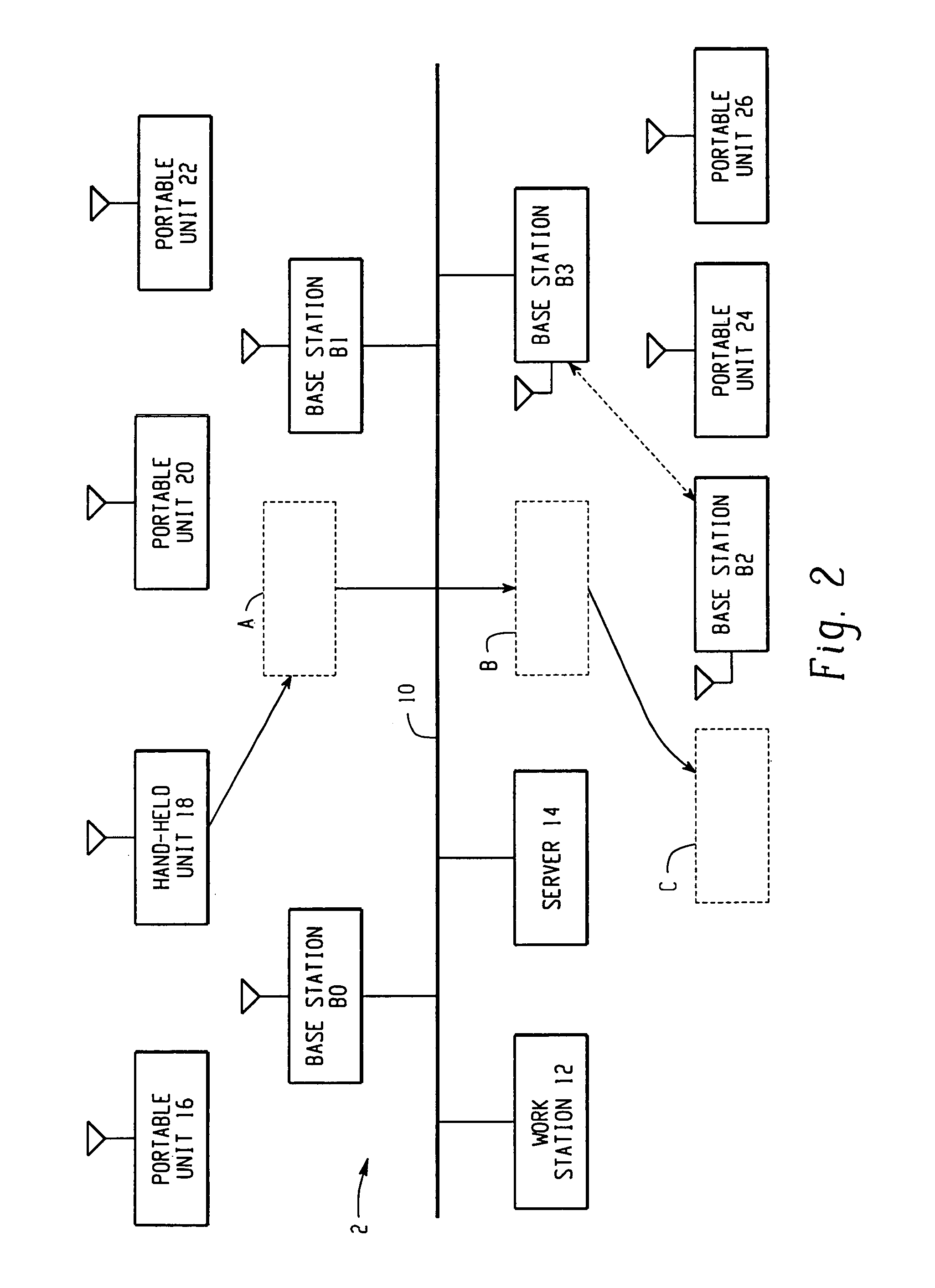
[0028]Referring now to FIG. 2, there is shown a typical WLAN used ...


PUM


Abstract

A system and method for transmitting data communications through air using a radio. The invention allows the user to select from a number of predetermined output transmission powers. When a lower output transmission power is selected the current drain to the associated amplifier is decreased thereby conserving battery power of the radio. In addition, a detector diode circuit combined with an adjustable gain amplifier combine to provide a feedback mechanism whereby the output transmission power of the radio is held substantially constant over a broad range of temperatures.

Description

RELATED APPLICATION[0001]This application is a Continuation Application of application Ser. No. 09 / 750,818, filed Dec. 28, 2000 now U.S. Pat. No. 6,661,999.FIELD OF INVENTION[0002]The present invention relates generally to a power amplifier circuit for use in radios directed towards the transmission of wireless data communications. The invention is directed to the wireless local area network environment. More particularly, the present invention is directed towards a system for selectably increasing the transmission power of radios used in wireless computer networks over a broad range of temperatures and reducing the current drain as the transmit power of the radio is decreased so as to extend the battery life of such a device.BACKGROUND OF THE INVENTION[0003]The use of wireless networks has increased dramatically over the past few years. Wireless local area networks (“WLANs”) are now commonplace in the small office / home office (“SOHO”) environment as well as the commercial building ...

Claims


Application Information

Patent Timeline
Patent Type & Authority Patents(United States)
IPC IPC(8): H04B1/04H04B1/16
CPCH04B7/0602H04W52/52Y02B60/50H04B2001/0416
Inventor JOHNSON, GERALD B.FRIEDMANN, JAMES
Owner CISCO TECH INC
Why Eureka
Try Eureka