Method and system for battery management for mobile geofencing devices

a geofencing device and battery management technology, applied in the field of geofencing, can solve the problems of reducing the life of the internal battery, no technology available on the mobile geofencing apparatus itself or remotely via the internet or other network to determine, and no easy way to estimate and calculate battery usage. the effect of battery li

Active Publication Date: 2021-06-17
SVR TRACKING INC
View PDF1 Cites 1 Cited by
  • Summary
  • Abstract
  • Description
  • Claims
  • Application Information

AI Technical Summary

Benefits of technology

[0020]Location information for a vehicle, temperature information for the vehicle and battery information for the internal battery on the mobile geofence apparatus is automatically, continuously and periodically collected and sent during a connection interval in real-time to an external network server network device via communications network for tracking the vehicle in real-time. The battery information is displayed on the mobile geofence apparatus for a viewer and is also sent to an external server network device for display to a viewer. Internal battery usage is automatically managed internally on the mobile geofence apparatus using the collected location, battery and temperature information. The internal battery on the mobile geofence apparatus can also be automatically managed externally via the external server network device using the collected location, battery and temperature information. The connection interval is adjusted automatically and dynamically by mobile geofence apparatus itself or by the external network server to save battery life on the internal battery when the vehicle is in extreme hot or cold weather conditions and during times when the vehicle is an area with poor network connectivity or coverage.

Problems solved by technology

There are several problems associated with the internal batteries associated with mobile geofence apparatus.
One problem is that in climates including warm and humid weather, and extreme cold weather, the operational lifetime of the internal batteries are reduced.
However, currently there is no technology available on the mobile geofencing apparatus itself or remotely via the Internet or other network to determine when a battery needs to be replaced.
Another problem is that there is no easy way to estimate and calculate battery usage for given temperature / humidity situation.
Another problem is that there is no easy way to determine an ambient temperature of a battery in a mobile geofence apparatus.
Another problem is that there no easy way to determine how changing a reporting frequency for the mobile geofencing apparatus affects an ambient temperature of the battery.
Such frequent reporting can significantly reduce the battery life and battery charge of an internal battery.
Another problem is that there is no easy way to adjust battery usage when a voltage level of an internal battery mobile geofencing apparatus falls below a pre-determined critical voltage level.
Another problem is that there is no easy way to estimate a current location of a vehicle if the internal battery mobile geofencing apparatus falls below a pre-determined critical voltage level or is in an area with no or limited network connectivity to provide current temperature and location data.
Another problem is that there is not a graphical battery meter on mobile geofencing apparatus or a graphical battery meter for any server network device the mobile geofencing apparatus connects to.
However, none of these problems solve of the problems associated with battery management of mobile geofencing devices.

Method used


Image

  • Method and system for battery management for mobile geofencing devices
  • Method and system for battery management for mobile geofencing devices
  • Method and system for battery management for mobile geofencing devices

Examples


Embodiment Construction

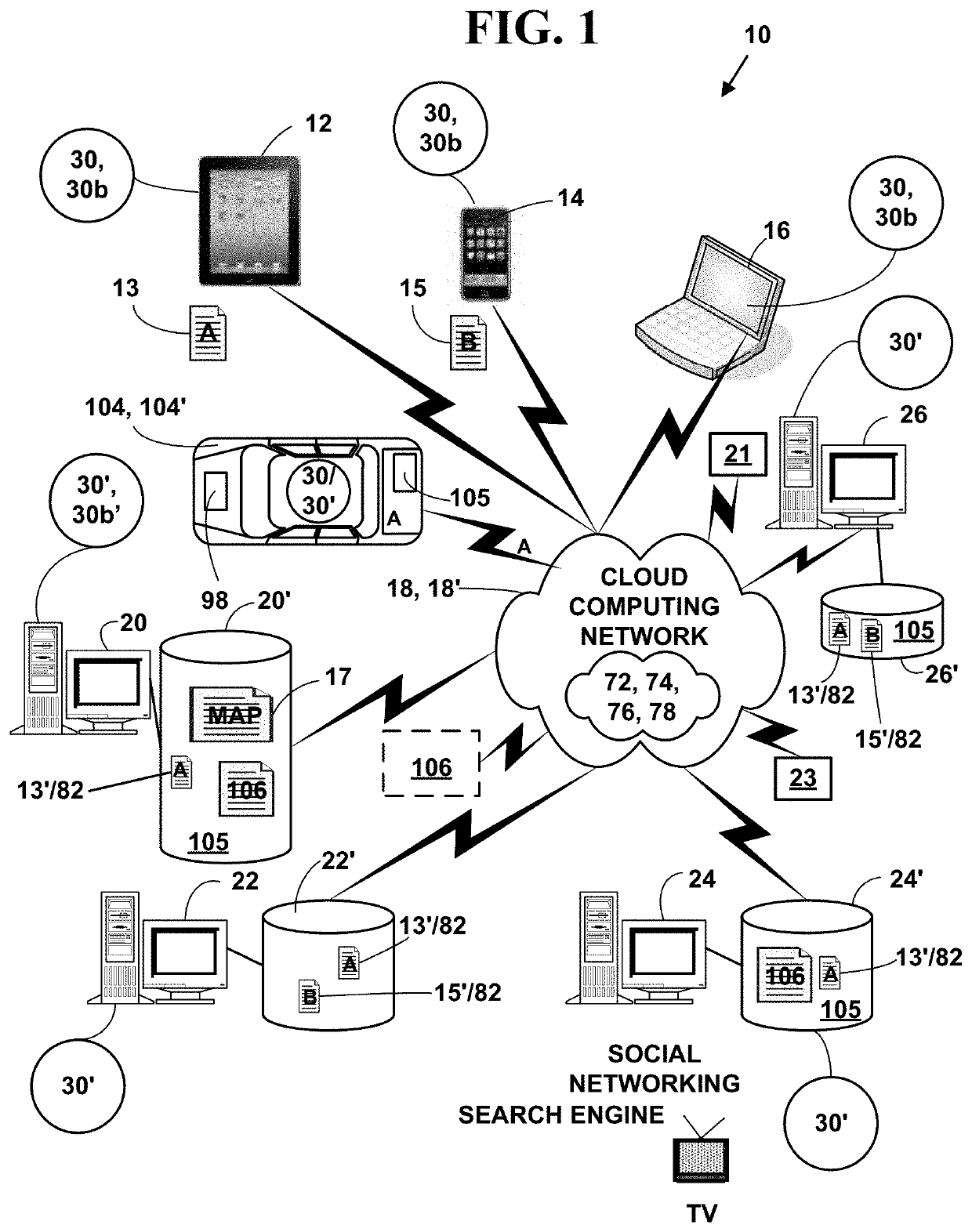
[0045]FIG. 1 is a block diagram illustrating an exemplary electronic information system 10. The exemplary electronic system 10 includes, but is not limited to, one or more target network devices 12, 14, 16 (only three of which are illustrated) each with one or more processors and each with a non-transitory computer readable medium.

[0046]The one or more target network devices 12, 14, 16 include, but are not limited to, multimedia capable desktop and laptop computers 16, tablet computers 14, facsimile machines, mobile phones 12, surface computers 21, wearable network devices 23, non-mobile phones, smart phones, Internet phones, Internet appliances, personal digital / data assistants (PDA), two-way pagers, digital cameras, portable game consoles (Play Station Portable by Sony, Game Boy by Sony, Nintendo DSI, etc.), non-portable game consoles (Xbox by Microsoft, Play Station by Sony, Wii by Nintendo, etc.), cable television (CATV), satellite television (SATV) and Internet television set-t...


PUM

PropertyMeasurementUnit
radio frequenciesaaaaaaaaaa
timeaaaaaaaaaa

Abstract

A method and system for battery management for a mobile geofence apparatus. Location information for a vehicle, temperature information for the vehicle and battery information for the internal battery on the mobile geofence apparatus is automatically, continuously and periodically collected and sent during a connection interval in real-time to an external network server network device via communications network for tracking the vehicle in real-time. The battery information is displayed on the mobile geofence apparatus for a viewer and is also sent to an external server network device for display to a viewer. Internal battery usage is automatically managed internally on the mobile geofence apparatus using the collected location, battery and temperature information. The internal battery on the mobile geofence apparatus can also be automatically managed externally via the external server network device using the collected location, battery and temperature information. The connection interval is adjusted automatically and dynamically by mobile geofence apparatus itself or by the external network server to save battery life on the internal battery when the vehicle is in extreme hot or cold weather conditions and during times when the vehicle is an area with poor network connectivity or coverage.

Description

CROSS REFERENCES TO RELATED APPLICATIONS[0001]This utility application claims priority to U.S. Provisional patent application No. 62 / 948,251, filed Dec. 14, 2019, the contents of which are incorporated by reference.FIELD OF INVENTION[0002]This application relates to geofencing. More specifically, it relates to a method and system for battery management of geofencing devices.BACKGROUND OF THE INVENTION[0003]Impound yards are used to store vehicles that have been towed away by private companies, at the request of law enforcement, at the request of a car dealer, at the request of finance companies, etc.[0004]A “geofence” is a virtual geographic boundary, defined by Global Positioning System (GPS), Radio Frequency Identifier (RFID) technology or other wireless location technologies that enables a response to be triggered when a mobile geofencing apparatus enters or leaves the geographic boundary of an actual area (e.g., car lot, impound lot, homeowner driveway, etc.) and when it is nece...

Claims


Application Information

Patent Timeline
Patent Type & Authority Applications(United States)
IPC IPC(8): G07C5/00G06F1/26G07C5/08H04L29/08G01K3/00
CPCG07C5/008G06F1/263G07C5/0825G01S19/42H04L67/18G01K3/005H04L67/12G06F1/3212G06F1/325G06F1/3278H04W4/38H04W4/021Y02D10/00Y02D30/70H04L67/52
Inventor WELLS, MARK A.PEACHEY, EZRA T.SEPPANEN, JORMA A.
Owner SVR TRACKING INC
Why Eureka
Try Eureka