Check patentability & draft patents in minutes with Patsnap Eureka AI!

Pneumatic tire

a pneumatic tire and tire body technology, applied in the field of pneumatic tires, can solve the problems of uneven wear more readily uneven wear is more readily in the shoulder and the contact patch length in the center region of the tread portion is relatively increased, so as to reduce rolling resistance and effectively suppress uneven wear in the shoulder region and the center region of the tread portion

Active Publication Date: 2021-11-23
THE YOKOHAMA RUBBER CO LTD
View PDF10 Cites 0 Cited by
  • Summary
  • Abstract
  • Description
  • Claims
  • Application Information

AI Technical Summary

Benefits of technology

This design effectively reduces rolling resistance and suppresses uneven wear in both the shoulder and center regions, maintaining tire durability and preventing rolling resistance degradation.

Problems solved by technology

A demerit of employing a rectangular contact patch shape is that uneven wear tends to occur more readily in a shoulder region of the tread portion.
However, in the case of the structure of a belt layer increasing the rigidity in the tire circumferential direction of an end portion of the belt layer, contact patch length in a center region of a tread portion is relatively increased and uneven wear occurs more readily in the center region of the tread portion.
This may cause the rolling resistance to be degraded.
In this way, reducing rolling resistance and suppressing uneven wear in a shoulder region and a center region of a tread portion in a compatible manner is problematic.
When the end position of the belt reinforcing layer and the position of the shoulder main groove are located in the same position, cracking more readily occurs in the groove bottom of the shoulder main groove.

Method used


Image

  • Pneumatic tire
  • Pneumatic tire
  • Pneumatic tire

Examples


examples

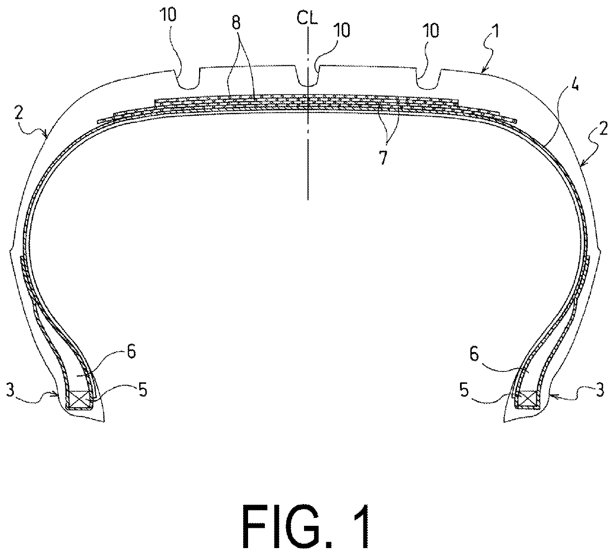
[0059]Pneumatic tires according to Conventional Example 1, Comparative Example 1, and Examples 1 to 7 were manufactured with a tire size of 205 / 55R16 91V and including a carcass layer mounted between a pair of bead portions, two belt layers disposed outward of the carcass layer in the tire radial direction in the tread portion, and a belt reinforcing layer disposed outward of the two belt layers in the tire radial direction. The belt layer structure, the belt reinforcing layer structure, and the rectangular ratio of the contact patch shape were set as indicated in Table 1.

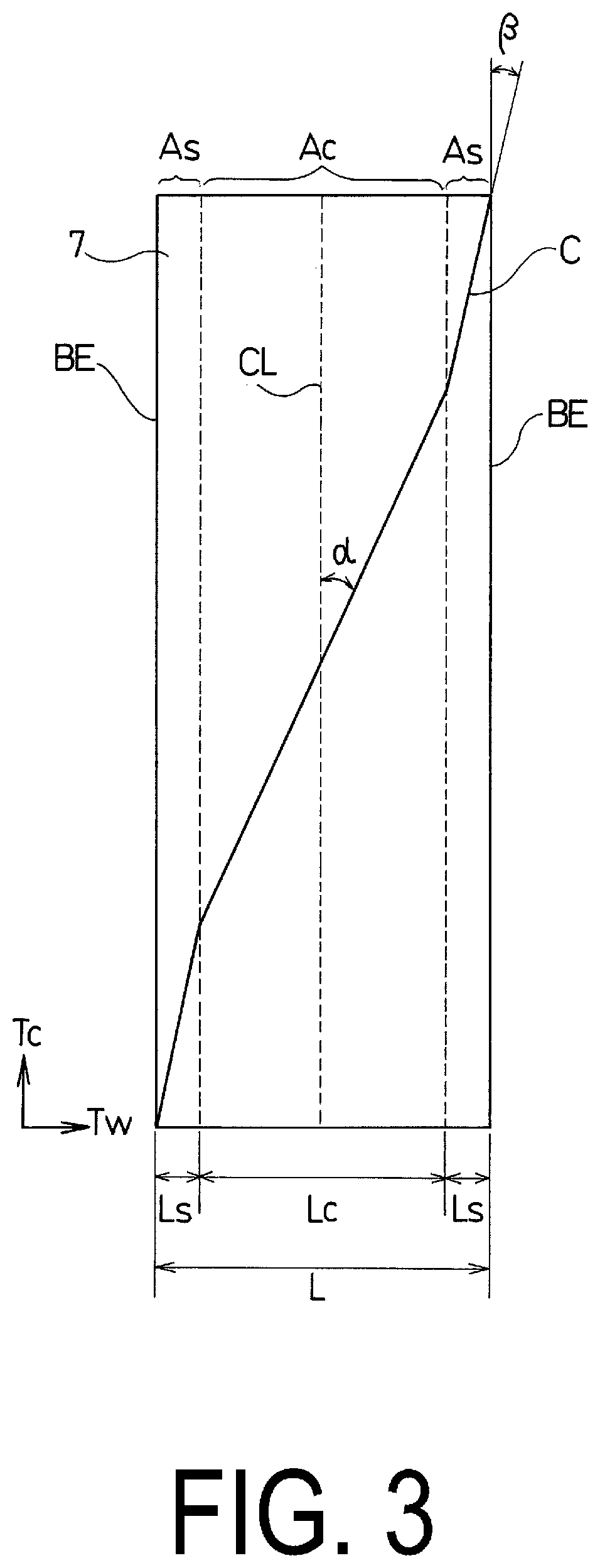
[0060]In Conventional Example 1, a typical belt layer in which the inclination angle α of the belt cord with respect to the tire circumferential direction at the tire center position and inclination angle β of the belt cord with respect to the tire circumferential direction at the belt end position are identical was used, as well as a belt reinforcing layer (full cover) that covers all of the belt layer.

[0061]In Co...


PUM


Abstract

A pneumatic tire includes a carcass layer and belt layers including belt cords inclined with respect to a circumferential direction, the belt cords of different layers being arranged in a criss-cross manner. In at least one belt layer, an inclination angle α of the belt cords with respect to the circumferential direction at a center position and an inclination angle β of the belt cords with respect to the circumferential direction at a belt end position satisfy 15°≤β<α≤35°. A maximum ground contact length L1 and a ground contact length L2 satisfy 0.8≤L2 / L1≤1.0, where L1 is the maximum ground contact length in the circumferential direction, W1 is a maximum ground contact width in a radial direction, and L2 is the ground contact length in the circumferential direction at a position 40% of W1 from the center position outward in a lateral direction.

Description

TECHNICAL FIELD[0001]The present technology relates to a pneumatic tire including a belt layer embedded in a tread portion and particularly relates to a pneumatic tire with reduced rolling resistance that can effectively suppress uneven wear in a shoulder region and a center region of a tread portion.BACKGROUND ART[0002]A pneumatic tire typically includes a carcass layer mounted between a pair of bead portions and a plurality of belt layers disposed outward of the carcass layer in the tire radial direction in a tread portion, wherein the plurality of belt layers each include a plurality of belt cords that are inclined with respect to the tire circumferential direction, and the plurality of belt cords of the different layers are disposed in a criss-cross manner.[0003]Recently, there has been great demand for a pneumatic tire for a passenger vehicle with reduced rolling resistance. To satisfy this demand, tires have been designed such that the tread portion has a generally rectangular...

Claims


Application Information

Patent Timeline
Patent Type & Authority Patents(United States)
IPC IPC(8): B60C9/20B60C11/03B60C11/04B60C11/12B60C9/22
CPCB60C9/20B60C9/2009B60C11/0306B60C11/0332B60C11/04B60C11/1204B60C11/1236B60C2009/2016B60C2009/2019B60C2009/2025B60C2009/2029B60C2009/2032B60C2009/229B60C2009/2257B60C2009/2271B60C2009/2295B60C2011/0344B60C2011/0358B60C2011/0383B60C2200/04Y02T10/86B60C9/2204
Inventor SHIBAI, TAKASHISHIDA, ZENICHIRO
Owner THE YOKOHAMA RUBBER CO LTD
Features
  • R&D
  • Intellectual Property
  • Life Sciences
  • Materials
  • Tech Scout
  • Unparalleled Data Quality
  • Higher Quality Content
  • 60% Fewer Hallucinations
Learn More