
Motor having increased passage for refrigerant for cooling coils

a technology of cooling coils and refrigerant, which is applied in the direction of cooling/ventilation arrangement, dynamo-electric components, and magnetic circuit shapes/forms/construction, etc., can solve the problems of reducing the efficiency of the motor, and achieve the effect of increasing the effect of cooling the coils with refrigerant and high-efficiency motors

Active Publication Date: 2021-11-30
PANASONIC INTELLECTUAL PROPERTY MANAGEMENT CO LTD
View PDF19 Cites 0 Cited by
  • Summary
  • Abstract
  • Description
  • Claims
  • Application Information

AI Technical Summary

Benefits of technology

This configuration effectively increases the cooling effects of the coils, achieving a highly efficient motor by ensuring refrigerant can pass through areas where heat accumulates, maintaining the space factor and efficiency of the motor.

Problems solved by technology

As a result, heat easily accumulates in the coils or teeth respectively wound with the coils, reducing efficiency of a motor.

Method used


Image

  • Motor having increased passage for refrigerant for cooling coils
  • Motor having increased passage for refrigerant for cooling coils
  • Motor having increased passage for refrigerant for cooling coils

Examples


modification example 1

[0063]The shape of each of corners 60A to 60D is not limited to a C-chamfered shape, but may be a desired shape. FIG. 4A is a view illustrating a cross section of one of teeth 42 and one of coils 5A according to modification example 1. FIG. 4B is a view illustrating another cross section of one of teeth 42 and one of coils 5A according to modification example 1. FIG. 4C is a view illustrating still another cross section of one of teeth 42 and one of coils 5A according to modification example 1. FIGS. 4A to 4C illustrate corners 60A or recesses 63 respectively having different shapes. For example, as illustrated in FIG. 4A, corner 60A may be formed into a cut-away part having a substantially rectangular cut-away shape to provide recess 63. As illustrated in FIG. 4B, corner 60A may be formed into a cut-away part having a substantially quadrant cut-away shape to allow an arc to face inward of each of coils 5A to provide recess 63. Furthermore, as illustrated in FIG. 4C, in each of the ...

modification example 2

[0068]FIG. 5 is a view illustrating a cross section of one of teeth 42 and one of coils 5A according to modification example 2. FIG. 5 illustrates third turn A3 of each of coils 5A and a corresponding one of teeth 42. As illustrated in FIG. 5, opposing surface 62 of one of coils 5A faces adjacent one of coils 5A, and is provided with a plurality of recesses 63. As described above, refrigerant C easily flows between coils 5A adjacent to each other, compared with a case where refrigerant C flows between each of coils 5A and each of teeth 42. The plurality of recesses 63 provided on opposing surface 62, increasing surface areas of parts that come into contact with refrigerant C. Efficiency of cooling coils 5A thus further increases. Even when corners 60C, 60D lying on opposing surface 62 are each formed into a cut-away part, surface areas on opposing surface 62 can be increased.

[0069]An uneven shape of opposing surface 62 is not limited to have the shape illustrated in FIG. 5. Whether ...


PUM


Abstract

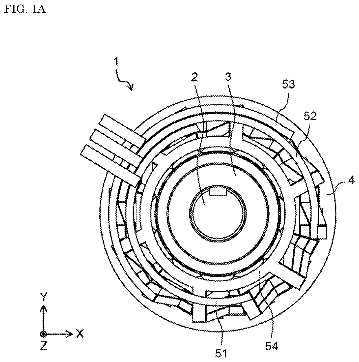
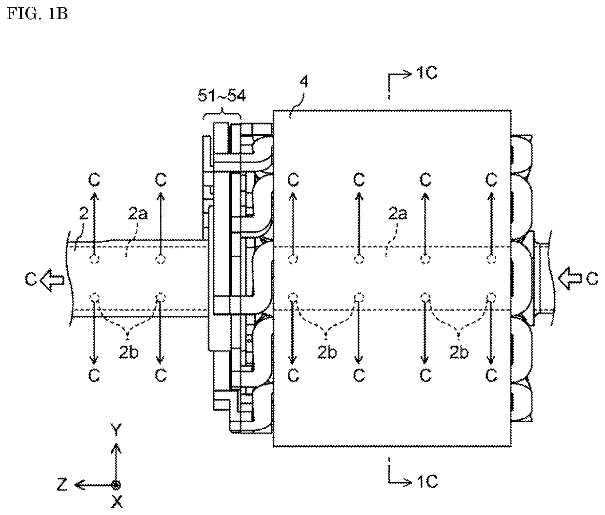
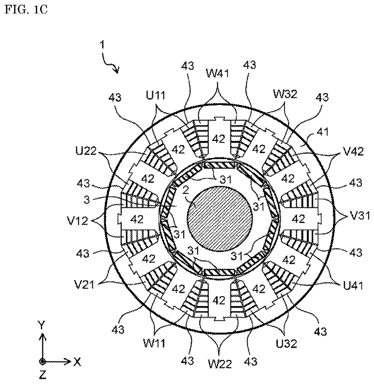
A motor includes a stator including a stator core and teeth respectively protruding from the stator core, and coils respectively wound onto the teeth n (n is an integer of 1 or greater) turns including first to n-th turns. The coils are each made from a conductive member having a polygonal cross section. On a cross section obtained when one of the coils is cut in a corresponding one of directions of protrusion of the teeth from the stator core, the one of the coils includes a recess on at least either a first opposing surface representing an opposing surface to a corresponding one of the teeth or a second opposing surface representing an opposing surface to another one of the coils, which is wound onto adjacent one of the teeth. A space allowing refrigerant used for cooling the coils to pass through is provided between the recess and at least either the first opposing surface or the second opposing surface.

Description

TECHNICAL FIELD[0001]The technique disclosed herein relates to a structure of coils in a motor.BACKGROUND ART[0002]Industry motors and on-vehicle motors have been highly demanded in recent years. In particular, a low cost but highly efficient motor has been demanded.[0003]As a method for improving efficiency of a motor, increasing a space factor of coils respectively disposed within slots of a stator has been known. Increasing a space factor of coils can suppress a loss due to a current flowing into the coils when a motor is driven.[0004]As a method for increasing a space factor of coils, such a configuration has been proposed that molded coils made of a copper material are respectively disposed within slots (e.g., see PTL 1).[0005]Heat is a factor of lowering efficiency of a motor. Such a method is known that refrigerant is allowed to circulate in a motor to suppress a rise in temperature (e.g., see PTL 2).[0006]As a space factor of coils increases, an empty space in slots reduces,...

Claims


Application Information

Patent Timeline
Patent Type & Authority Patents(United States)
IPC IPC(8): H02K3/24H02K1/20H02K3/18H02K9/19H02K5/20
CPCH02K3/24H02K1/20H02K3/18H02K5/20H02K9/19
Inventor HISHIDA, MITSUOKIYOSHIKAWA, YUICHIYAMAUCHI, HIROKAZUNUKADA, KEIICHIRO
Owner PANASONIC INTELLECTUAL PROPERTY MANAGEMENT CO LTD
Learn More