Motor

a technology of motors and coils, applied in the direction of dynamo-electric machines, dynamo-electric circuits, electrical apparatus, etc., can solve the problems of lowering the efficiency of motors, heat is a factor of lowering efficiency, etc., and achieve the effect of high-efficiency motors and increased heat radiation effects of coils

Active Publication Date: 2020-02-06
PANASONIC INTELLECTUAL PROPERTY MANAGEMENT CO LTD
View PDF15 Cites 1 Cited by
  • Summary
  • Abstract
  • Description
  • Claims
  • Application Information

AI Technical Summary

Benefits of technology

[0012]According to the present disclosure, heat radiation effects due to the coils can be further increased, achieving a highly efficient motor.

Problems solved by technology

Meanwhile, heat is a factor of lowering efficiency of a motor.

Method used


Image

  • Motor
  • Motor
  • Motor

Examples


Embodiment Construction

[0019]An exemplary embodiment of the present disclosure will be described herein in detail with reference to the accompanying drawings. The preferable exemplary embodiment described below is a substantially mere example, and does not intend to limit the present disclosure, applications, and purposes.

Exemplary Embodiment

Motor Structure

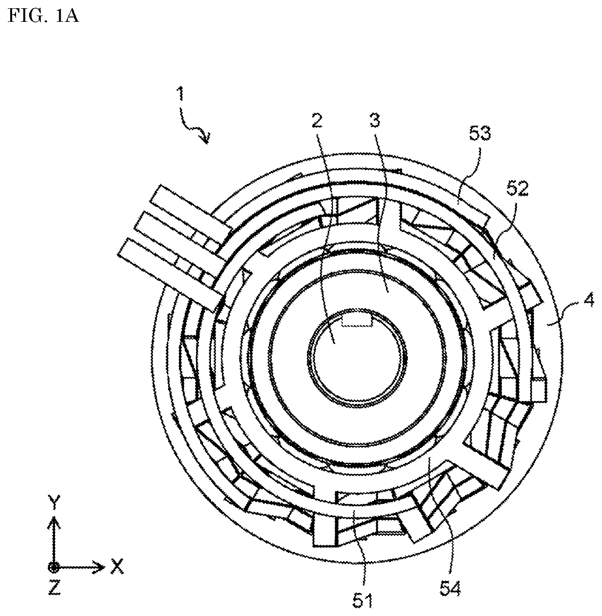
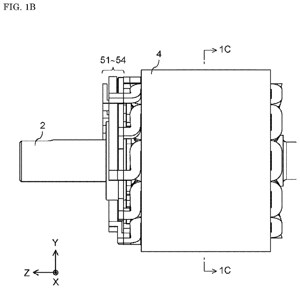
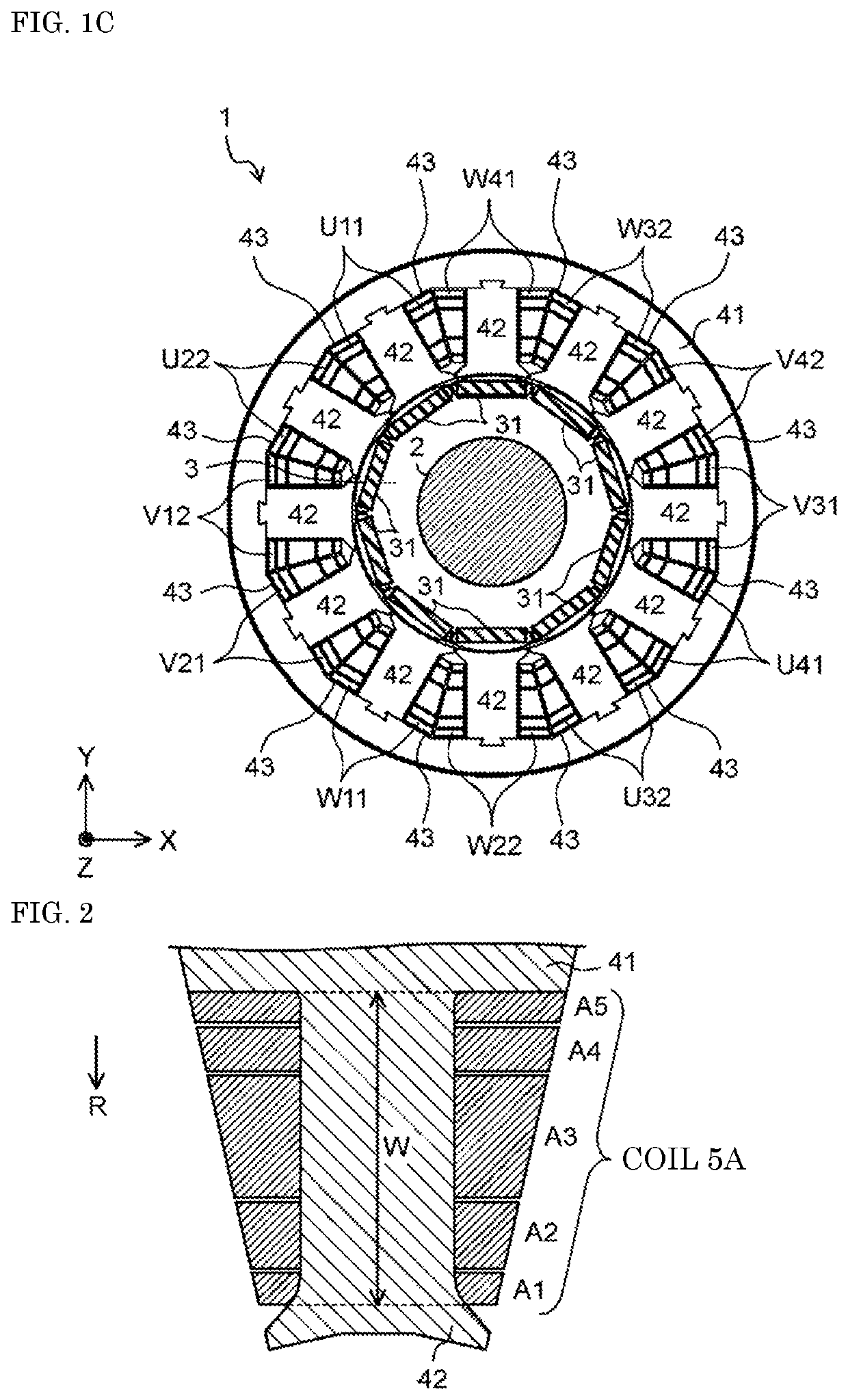
[0020]FIG. 1A is a top view illustrating a motor according to an exemplary embodiment. FIG. 1B is a side view illustrating the motor according to the exemplary embodiment. FIG. 1C is a cross-sectional view taken along line 1C-1C in FIG. 1B. However, the views do not illustrate a cover case, for example. Inside of the cover case (not illustrated), motor 1 includes shaft 2, rotor 3, stator 4, coils U11 to U41, V12 to V42, and W11 to W41, and bus bars 51 to 54.

[0021]In here, a longer direction (a direction vertical to a paper plane of FIG. 1A) of shaft 2 may sometimes be referred to as a Z-axis direction. Directions orthogonal to the Z-axis direction (dire...


PUM


Abstract

A motor includes a stator including a stator core and teeth respectively protruding from the stator core, and coils respectively wound onto the teeth n (n is an integer of 3 or greater) turns. In a cross section in a first direction representing each of directions of protrusion of the teeth from the stator core, a k-th (k is an integer, 1<k<n) turn of each of the coils lies at a center of a range wound with each of the coils onto the teeth in the first direction. The k-th turn of each of the coils is greater in cross-sectional area than each of a first turn and an n-th turn.

Description

TECHNICAL FIELD[0001]The present disclosure relates to motors. In particular, the present disclosure relates to a structure of coils in a motor.BACKGROUND ART[0002]Industry motors and on-vehicle motors have been highly demanded in recent years. In particular, a low cost but highly efficient motor has been demanded.[0003]As a method for improving efficiency of a motor, increasing a space factor of coils respectively disposed within slots of a stator has been known. Increasing a space factor of coils can suppress a loss due to a current flowing into the coils when a motor is driven.[0004]As a method for increasing a space factor of coils, such a configuration has been proposed that molded coils made of a copper material are respectively disposed within slots (e.g., see PTL 1).[0005]When coils are produced through molding or forming, for example, the coils have been each made uniform in cross-sectional area to achieve uniform resistance. Meanwhile, heat is a factor of lowering efficien...

Claims


Application Information

Patent Timeline
Patent Type & Authority Applications(United States)
IPC IPC(8): H02K3/20H02K1/14H02K21/16
CPCH02K1/146H02K2213/03H02K3/20H02K21/16H02K3/18H02K3/12
Inventor YOSHIKAWA, YUICHINUKADA, KEIICHIROKATO, YASUSHIYAMAUCHI, HIROKAZUHISHIDA, MITSUOKI
Owner PANASONIC INTELLECTUAL PROPERTY MANAGEMENT CO LTD
Why Eureka
Try Eureka