Aircraft propulsion system

a propulsion system and aircraft technology, applied in the direction of propellers, mechanical energy handling, transportation and packaging, etc., can solve the problem of high propulsor tip speed

Active Publication Date: 2022-06-21
ROLLS ROYCE PLC
View PDF29 Cites 0 Cited by
  • Summary
  • Abstract
  • Description
  • Claims
  • Application Information

AI Technical Summary

Benefits of technology

[0010]The first electric motor may be coupled to the first propulsor by an epicyclic gearbox comprising a sun gear, a plurality of planet gears mounted to a planet carrier, and a ring gear. Advantageously, the first propulsor may be configured to rotate at a slower speed than the rotor of the first electric motor. In the case of an electric motor having a rotor radially inward of a stator, relatively high rotational speeds can be achieved, giving high efficiency and power density. However, such high speeds result in high propulsor tip speeds where the rotor is directly coupled to the fan. Consequently, a highly efficient motor is provided, without the disadvantage of a high propulsor tip speed.
[0013]The first and / or second electric motors may comprise permanent magnet motors, and may comprise permanent magnet AC motors. Advantageously, electrical power does not have to be supplied across to the rotor, which greatly simplifies the electrical system. Where the first motor comprises a permanent magnet motor, the rotor permanent magnets of the first motor may be mounted to a sun shaft coupled to the sun gear of the epicyclic gearbox. Where the second motor comprises a permanent magnet motor, the rotor permanent magnets of the second motor may be mounted to an inner annulus of a fan rotor disc of the second propulsor.

Problems solved by technology

However, such high speeds result in high propulsor tip speeds where the rotor is directly coupled to the fan.

Method used


Image

  • Aircraft propulsion system
  • Aircraft propulsion system
  • Aircraft propulsion system

Examples


Embodiment Construction

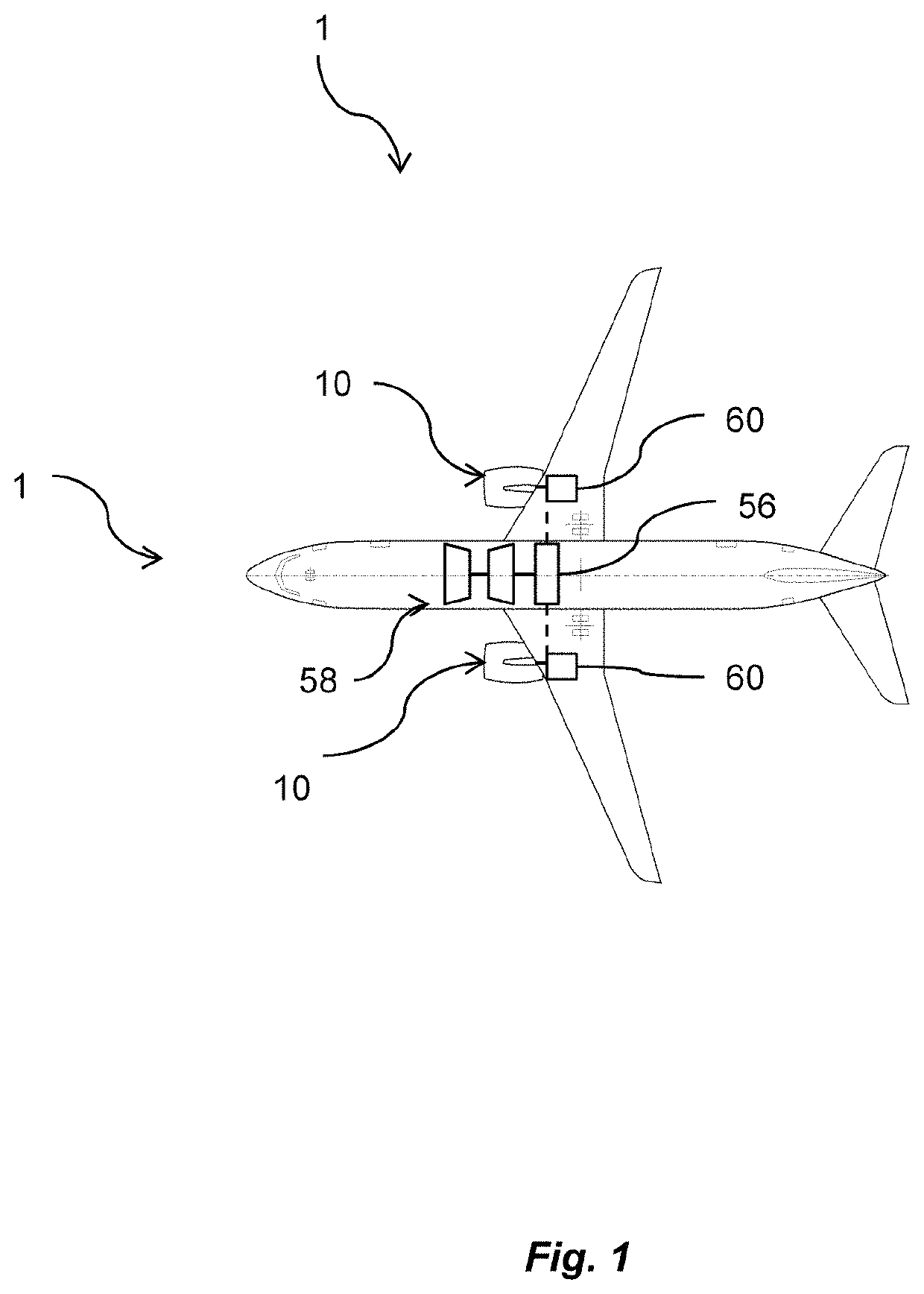
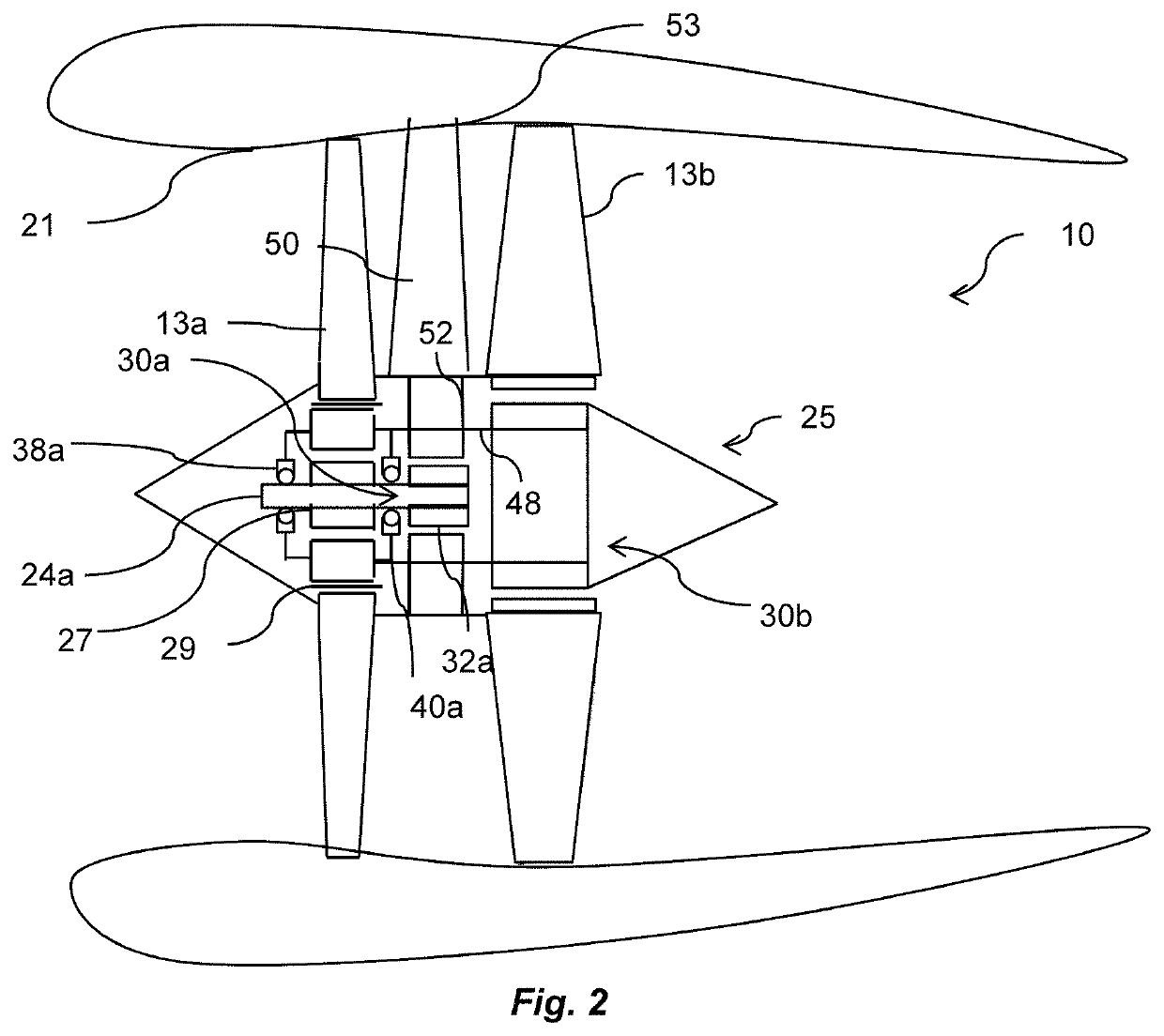
[0027]With reference to FIG. 1, an aircraft 1 is shown having a propulsion system 10. The propulsion system 10 is shown in further detail in FIGS. 2 to 4, and is in the form of a ducted fan, having first and second propulsors in the form of first and second fans 13a, 13b. Each fan 13a, 13b is enclosed within a fan duct 21, and is mounted to a core nacelle 25. Each fan 13a, 13b is driven by a respective electric motor 30a, 30b. Each electric motor is supplied with electric power from a power source. In the present embodiment, the power source comprises a gas turbine engine 58, which drives a generator 56. An additional power source in the form of one or more chemical batteries 60 is also provided.

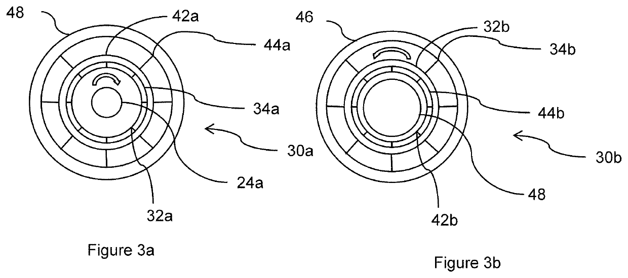
[0028]Each fan 13a, 13b is driven by a respective electric motor 30a, 30b. The first and second motors 30a, 30b are shown in further detail in FIG. 3. The first motor 30a comprises a rotor 32a comprising a plurality of permanent magnets 34a. The rotor 32a is configured to rotate in operation...


PUM


Abstract

An aircraft propulsion system comprises first and second co-axial propulsors, one of the first and second propulsor being positioned forward of the other propulsor. A first electric motor is configured to drive the first propulsor, and a second electric motor is configured to drive the second propulsor. The first electric motor comprising a rotor radially inwardly of the stator, and the second electric motor comprises a rotor radially outwardly of the stator. The stator of the first electric motor is mounted to the stator of the second electric motor.

Description

CROSS-REFERENCE TO RELATED APPLICATIONS[0001]This application is based upon and claims the benefit from priority British Patent Application No. 1814255.4 filed 3 Sep. 2018, British Patent Application No. 1814256.2 filed 3 Sep. 2018, and British Patent Application No. 1814869.2 filed 13 Sep. 2018, the entire contents of each of which are incorporated herein.BACKGROUNDTechnical Field[0002]The present disclosure concerns a propulsion system for an aircraft.Description of the Related Art[0003]In the pursuit of reduced fuel burn and / or other emissions, electric aircraft propulsors are being developed. In an electric aircraft propulsor, a ducted fan or open rotor propeller is driven by an electric motor by electrical power provided from one or both of a battery and a prime mover such as an internal combustion engine driven electrical generator. Where the electric power for the electric motors is provided by an internal combustion engine, such a system is known as a “hybrid electric propul...

Claims


Application Information

Patent Timeline
Patent Type & Authority Patents(United States)
IPC IPC(8): B64C11/48B64D27/24H02K7/116H02K7/14B64C11/00H02K16/02H02K16/00H02K21/22H02K21/14
CPCB64C11/48B64C11/001B64D27/24H02K7/116H02K7/14H02K16/00H02K16/02H02K21/14H02K21/22B64D2027/026B64D27/00B64D27/02B64D2027/005Y02T50/60
Inventor HARVEY, GILES E.
Owner ROLLS ROYCE PLC
Why Eureka
Try Eureka