Spring-loaded inner-conductor contact element

a contact element and inner-conductor technology, applied in the direction of coupling contact members, coupling device connections, coupling/insulating coupling contact members, etc., can solve the problems of increasing assembly and logistics unnecessarily, disadvantageous geometric expansion of board-to-board plug connectors, and being able to fulfill. , to achieve the effect of reducing stiffness, reducing stiffness, and reducing stiffness

Active Publication Date: 2021-12-07
ROSENBERGER HOCHFREQUENZTECHNIK GMBH & CO KG
View PDF18 Cites 3 Cited by
  • Summary
  • Abstract
  • Description
  • Claims
  • Application Information

AI Technical Summary

Benefits of technology

[0026]With regard to its function as insulator element, the elastic element is arranged between the at least one inner conductor and the outer conductor of the high-frequency contact device and is thus formed approximately sleeve-shaped. In a central area between two end areas, which are each adjacent to an axial end of the elastic element, the elastic element preferably has a reduced stiffness.
[0027]This reduced stiffness of the elastic element in its central area advantageously effects that the largest elastic deformation of the elastic element appears predominantly in this central area and not in the two end areas.
[0028]The reduced stiffness in the central area of the elastic element is preferably realized by means of a reduced outer diameter and by means of several slots, which run in the longitudinal axial direction and which are located between the outer and inner surface of the elastic element, which is molded to be hollow. In the case of a compressive force acting in the longitudinal axial direction, the reduced outer diameter of the central area increases through these slots, which run in the longitudinal axial direction, while the axial longitudinal extension of the central area of the elastic element advantageously shortens. The reduced outer diameter in the central area can thereby expand up to the size of the non-reduced outer diameter in the end areas of the elastic element.
[0029]An additionally reduced stiffness is attained in that at least one recess is in each case provided within the central area of the sleeve-shaped elastic element on the inner and / or outer surface. This at least one recess leads to an additional reduction of the cross section of the elastic element in the area of the recess. The individual recesses are preferably arranged at the points of the central area, at which a change of the elastic element in the radial direction appears particularly strongly in response to contraction.
[0030]Due to the reduced outer diameter, the individual slots, and the individual recesses in the central area of the elastic element, the effective permittivity is reduced in a section of the high-frequency transmission path, in which the central area of the elastic element is located. The characteristic wave impedance in this section of the high-frequency transmission path thus increases. To realize a characteristic wave impedance, which is adapted over the entire longitudinal extension of the high-frequency transmission path, the outer diameter of the at least one inner conductor in the section of the high-frequency transmission path, in which the central area of the elastic element is located, is increased as compared to the sections of the high-frequency transmission path, in which the end areas of the elastic element are located in each case.

Problems solved by technology

The realization of a board-to-board plug connector based on SLC technology for the transmission of high-frequency signals disadvantageously still requires too many individual parts, which increases the costs for the assembly and the logistics unnecessarily.
In addition, board-to-board plug connectors of this type disadvantageously also have a geometric expansion, which is too large to be able to fulfill future requirements with regard to the distance between several high-frequency contact elements in SLC technology, which are each positioned in a grid or in a row.

Method used


Image

  • Spring-loaded inner-conductor contact element
  • Spring-loaded inner-conductor contact element
  • Spring-loaded inner-conductor contact element

Examples


Embodiment Construction

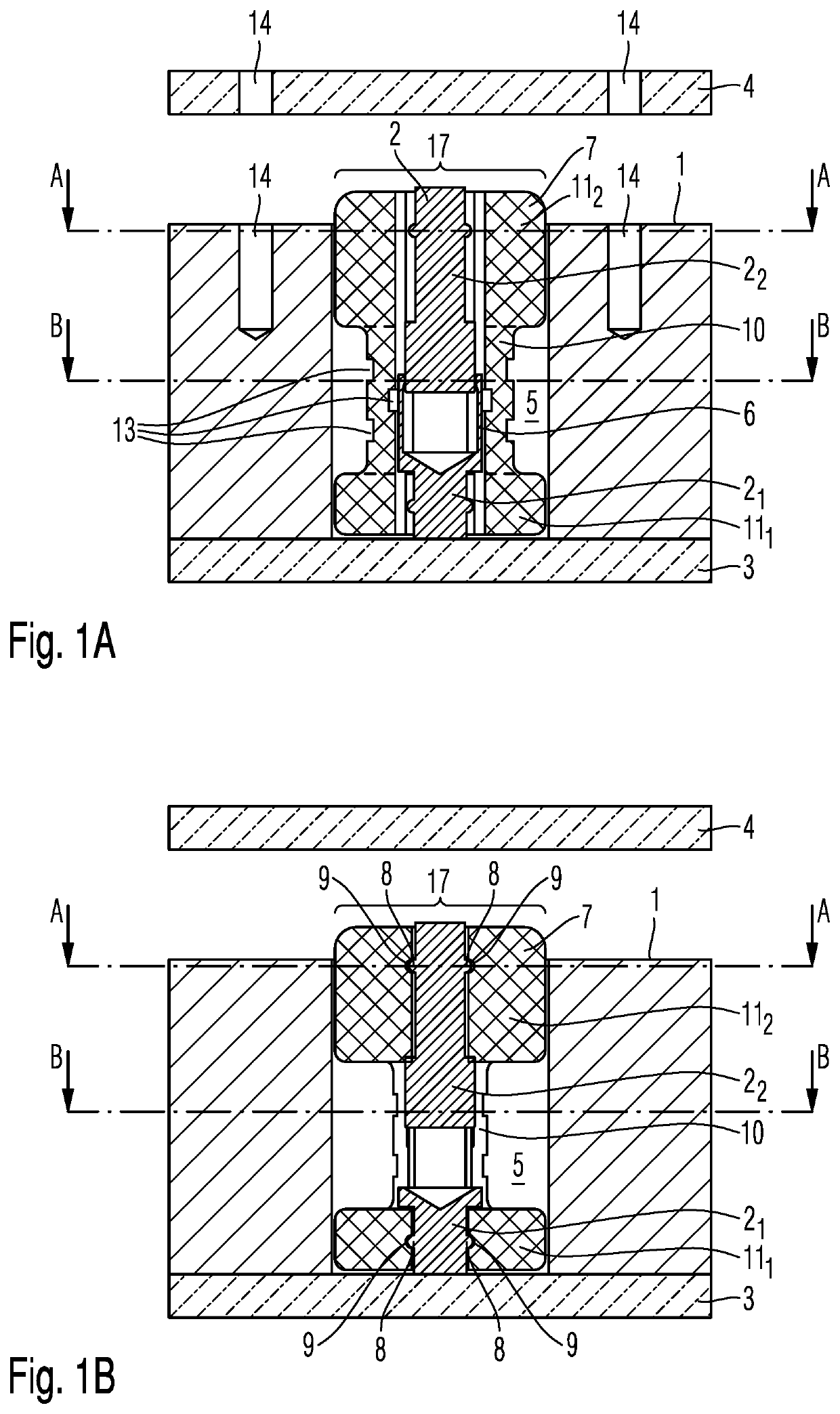
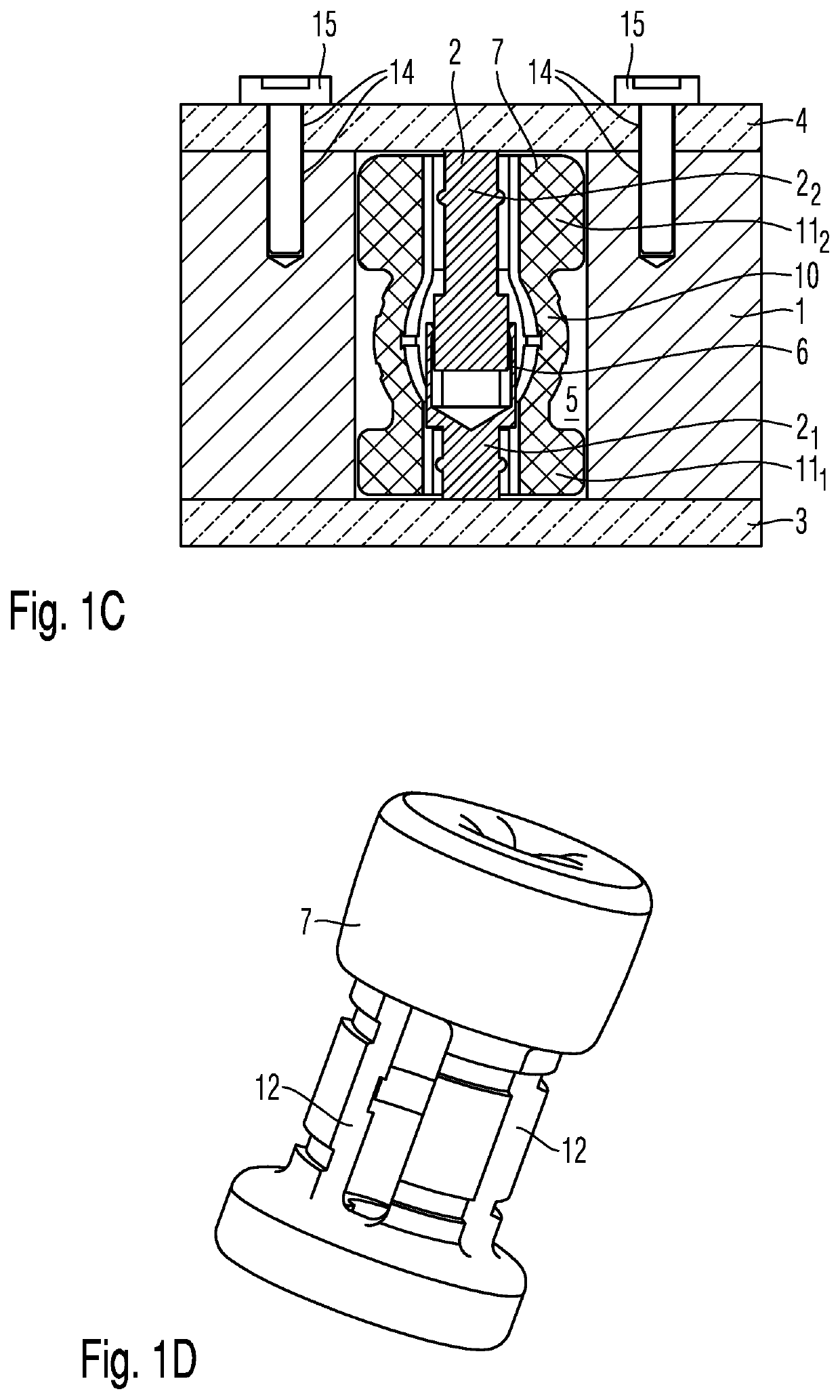
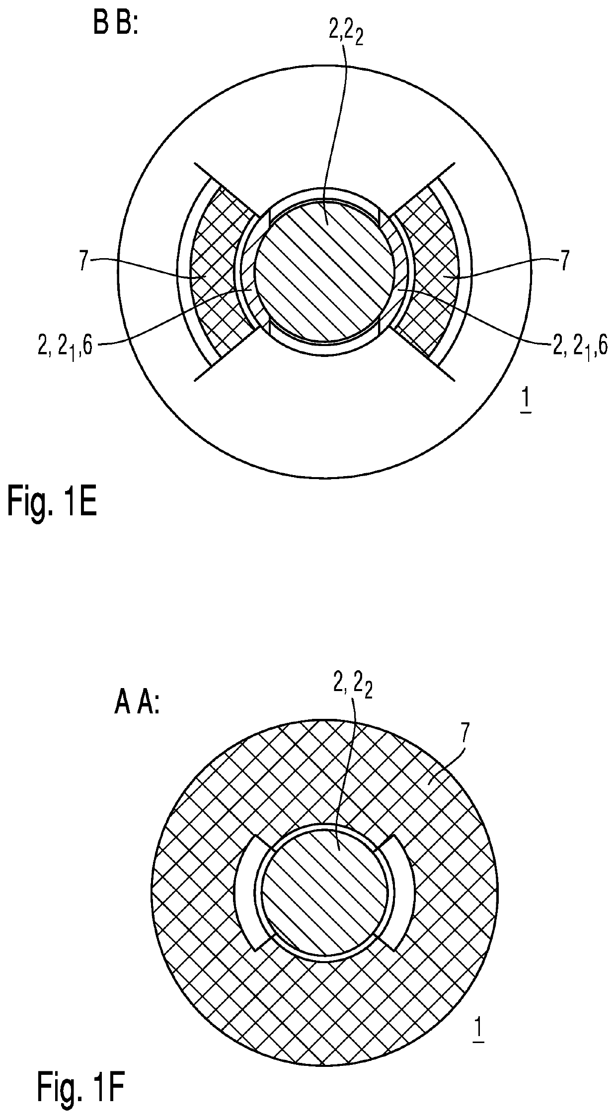
[0050]Before an assembly in accordance with the present disclosure comprising a second alternative of a spring-loaded inner-conductor contact element for transmitting a differential high-frequency signal, i.e. a symmetrical high-frequency signal, between two high-frequency components will be described on the basis of FIGS. 2A to 2C, an assembly in accordance with the present disclosure comprising a first alternative of a spring-loaded inner-conductor contact element for transmitting an asymmetrical high-frequency signal will be introduced in detail on the basis of FIGS. 1A to 1F, which now follow:

[0051]In the case of a transmission of an asymmetrical high-frequency signal, the high-frequency transmission path is embodied as coaxial transmission path. For this purpose, the coaxial transmission path preferably has a metallic outer-conductor contact element 1 and a single metallic inner conductor 2, which is arranged coaxially to the outer-conductor contact element 1 within the outer-c...


PUM

PropertyMeasurementUnit
outer circumferenceaaaaaaaaaa
lengthaaaaaaaaaa
elasticaaaaaaaaaa

Abstract

The invention relates to a spring-loaded inner-conductor contact element comprising at least one inner conductor and an elastic element that surrounds the at least one inner conductor. The axial dimension of the at least one inner conductor can be modified. The at least one inner conductor is metallic. The elastic element is made of an electrically insulating material and is attached to each inner conductor.

Description

FIELD OF THE INVENTION[0001]The present disclosure relates to a spring-loaded inner-conductor contact element, an elastic element, which is contained in this spring-loaded inner-conductor contact element, and an assembly, which contains this spring-loaded inner-conductor contact element.TECHNICAL BACKGROUND[0002]So-called board-to-board plug connectors have established themselves as quick data transmission interface for high-frequency signals between two high-frequency components, for example two printed circuit boards, each comprising a high-frequency electronics. These board-to-board plug connectors have the task of realizing an electrical connection for high-frequency signals between the two high-frequency components with adapted characteristic wave impedance.[0003]In a particular form, the outer-conductor contacts on the two high-frequency components are firmly connected to one another via an electroconductive intermediate component, which serves as outer conductor. This electro...

Claims


Application Information

Patent Timeline
Patent Type & Authority Patents(United States)
IPC IPC(8): H01R13/41H01R12/71H01R13/15
CPCH01R13/41H01R12/714H01R13/15H01R12/73H01R13/17H01R13/2407H01R24/50
Inventor SCHWARZ, BENEDIKTGRUBER, ANDREASHEUBECK, JOHANNES
Owner ROSENBERGER HOCHFREQUENZTECHNIK GMBH & CO KG
Why Eureka
Try Eureka