
Connector shroud

a technology of connectors and weather shields, applied in the direction of optical elements, coupling device connections, instruments, etc., can solve the problems of limiting the density of connectors that can be installed in a panel, not being able to install connectors side by side, and requiring a larger spacing between connectors

Active Publication Date: 2021-12-21
ACSUPER TECH INC
View PDF8 Cites 0 Cited by
  • Summary
  • Abstract
  • Description
  • Claims
  • Application Information

AI Technical Summary

Benefits of technology

This design enhances the installation density of connectors by allowing single-handed operation, reducing the required spacing between connectors and enabling closer packing without compromising the locking mechanism's reliability.

Problems solved by technology

Since it is necessary to leave space for the operator's hands to manipulate the connector, it is not possible for connectors to be installed side-by-side close to one another.
This limits the density of connectors that can be installed in a panel and requires larger spacing between connectors on the panel.

Method used


Image

  • Connector shroud
  • Connector shroud
  • Connector shroud

Examples


first embodiment

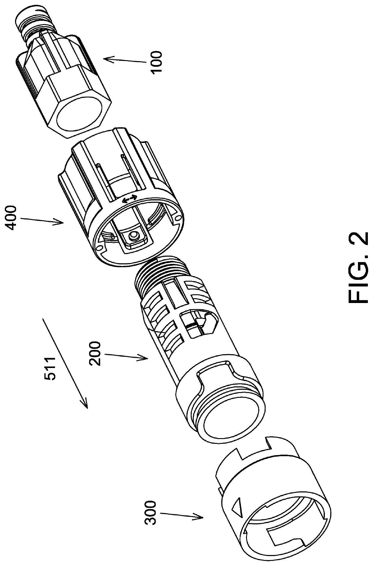
[0027]Referring to FIG. 2, which is an exploded view of the connector shroud according to the present invention. As shown in the figure, the connector shroud includes a cable gland 100, an inner housing 200, a coupling nut 300 and a lock nut 400. The cable gland 100, the inner housing 200, the coupling nut 300 and the lock nut 400 may be constructed of plastics by an injection molding process.

[0028]The cable gland 100 may be made from a flexible material and provide strain relief on cable (not shown) using materials and attachment techniques as are known in the art. The cable gland 100 has a hollow body whose lengthwise direction is parallel to a longitudinal direction 511. The cable gland 100 has a hexagonal shape at its front end for being coupled to the inner housing 200.

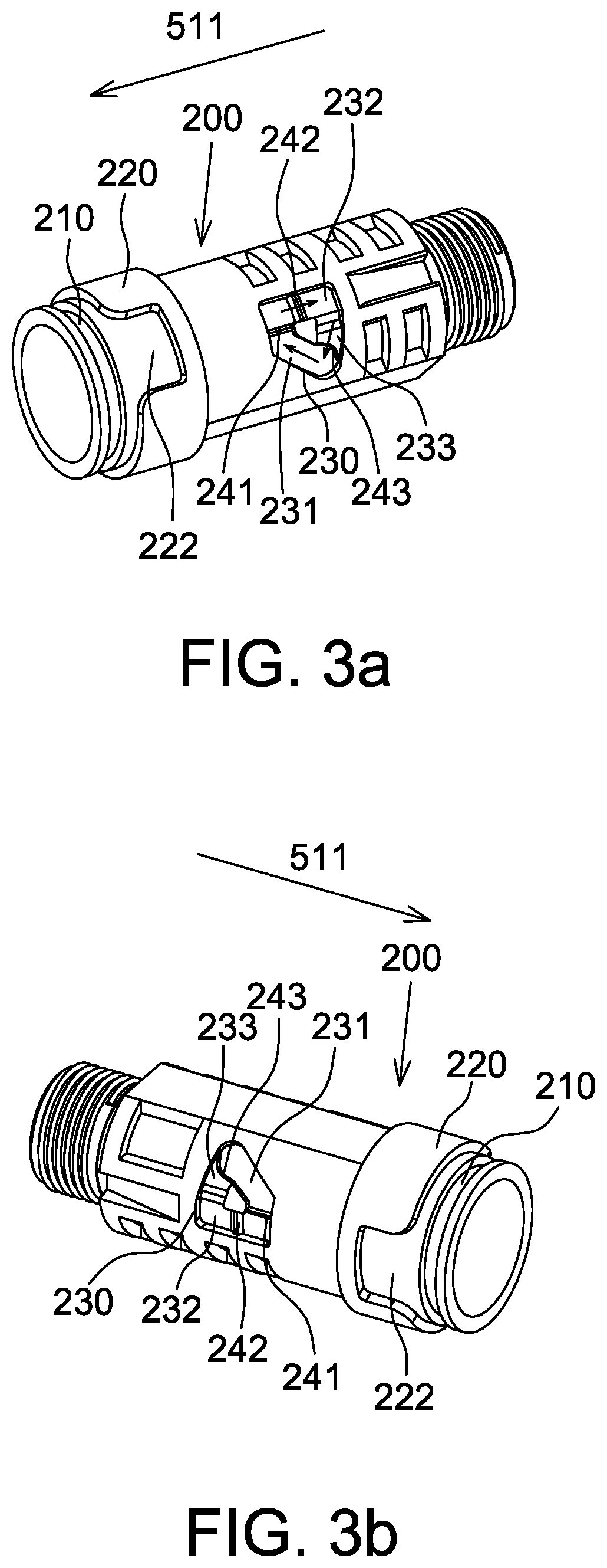
[0029]Referring to FIGS. 3a and 3b, the inner housing 200 is hollow and has a cylindrical body whose lengthwise direction is parallel to the longitudinal direction 511. An annular groove 210 is formed at the fron...

second embodiment

[0039]Referring to FIG. 9, which is an exploded view of the connector shroud according to the present invention. As shown in the figure, the connector shroud includes a cable gland 600, an inner housing 700, a coupling nut 800 and a lock nut 900. The cable gland 600, the inner housing 700, the coupling nut 800 and the lock nut 900 may be constructed of plastics by an injection molding process.

[0040]The cable gland 600 may be made from a flexible material and provide strain relief on cable (not shown) using materials and attachment techniques as are known in the art. The cable gland 600 has a hollow body whose lengthwise direction is parallel to a longitudinal direction 511. The cable gland 600 has a hexagonal shape at its front end for being coupled to the inner housing 700.

[0041]Referring to FIGS. 10a and 10b, the inner housing 700 is hollow and has a cylindrical body whose lengthwise direction is parallel to the longitudinal direction 511. An annular groove 710 is formed at the fr...


PUM


Abstract

The connector shroud of the present invention includes an inner housing, a coupling nut and a lock nut. The inner housing is hollow and a grooved control link is formed on the outer surface of the inner housing. The grooved control link extends in a longitudinal direction. The coupling nut is hollow and is sleeved onto the inner housing. A receiving recess is formed on the inner surface of the front end of the coupling nut for accommodating a protrusion provided on a flange. A tab protrudes from the rear end of the coupling nut. A control slot is formed on the tab and includes a first section and a second section. The second section communicates with the first section and extends in a direction not parallel to the longitudinal direction. The lock nut is hollow and sleeved onto the inner housing. A first pin and a second pin are formed on the inner surface of the lock nut. The first pin is disposed in the grooved control link. The second pin is located in the second section, wherein the movement of the lock nut causes the coupling nut to rotate.

Description

RELATED APPLICATION[0001]The present application claims priority to U.S. Provisional Application Ser. No. 63 / 035,065, filed on Jun. 5, 2020, and to Chinese Patent Application Number 202010948195.8, filed on Sep. 10, 2020, the disclosures of which are hereby incorporated by reference herein in their entirety.BACKGROUND1 Technical Field[0002]This invention generally relates to a connector shroud, more particularly, to an optical fiber connector weather shroud.2. Description of the Related Art[0003]Recently, the use of fiber optics for communications purposes has grown immensely. Data, voice, and other communication networks are increasingly using fiber optics to carry information. An optical fiber is generally a glass fiber configured to carry light. Individual fibers may be grouped into a line capable of carrying large amounts of data simultaneously.[0004]When constructing a fiber optic network, each individual fiber is generally connected to both a source and a destination device. A...

Claims


Application Information

Patent Timeline
Patent Type & Authority Patents(United States)
IPC IPC(8): G02B6/36G02B6/38
CPCG02B6/3894G02B6/3825G02B6/3807G02B6/381G02B6/3897H01R13/516H01R13/625G02B6/3891
Inventor TSENG, CHUNG-MING
Owner ACSUPER TECH INC
Learn More