Electric junction box

a technology of electric junction boxes and junction boxes, which is applied in the direction of electric/fluid circuits, electrical equipment, vehicle components, etc., can solve the problem of water accumulation on the bottom wall

Active Publication Date: 2021-12-21
YAZAKI CORP
View PDF8 Cites 0 Cited by
  • Summary
  • Abstract
  • Description
  • Claims
  • Application Information

AI Technical Summary

Benefits of technology

[0003]An in-vehicle electric junction box, in which an electronic component such as a fuse or a relay is detachably mounted on a face thereof, is known (see Patent Literature 1: JP-A-2017-127078 and Patent Literature 2: JP-A-2015-56994). This type of electric junction box includes one in which a connector (fitting component), in which an electronic component and an electric wire are assembled, is placed on an electronic component accommodating chamber of a housing in a stack manner. It is conceivable to provide the connector with a bottom wall in order to protect the electric wire assembled to the connector. However, when the bottom wall is provided, there is a concern that water accumulates on the bottom wall. Therefore, it is conceivable to provide a drain hole in the bottom wall, but simply providing the drain hole causes a problem of entering of water from the drain hole during high pressure washing or the like.

Problems solved by technology

However, when the bottom wall is provided, there is a concern that water accumulates on the bottom wall.
Therefore, it is conceivable to provide a drain hole in the bottom wall, but simply providing the drain hole causes a problem of entering of water from the drain hole during high pressure washing or the like.[Patent Literature 1] JP-A-2017-127078[Patent Literature 2] JP-A-2015-56994

Method used


Image

  • Electric junction box
  • Electric junction box
  • Electric junction box

Examples


Embodiment Construction

[0014]A specific embodiment according to the present invention will be described with reference to the drawings.

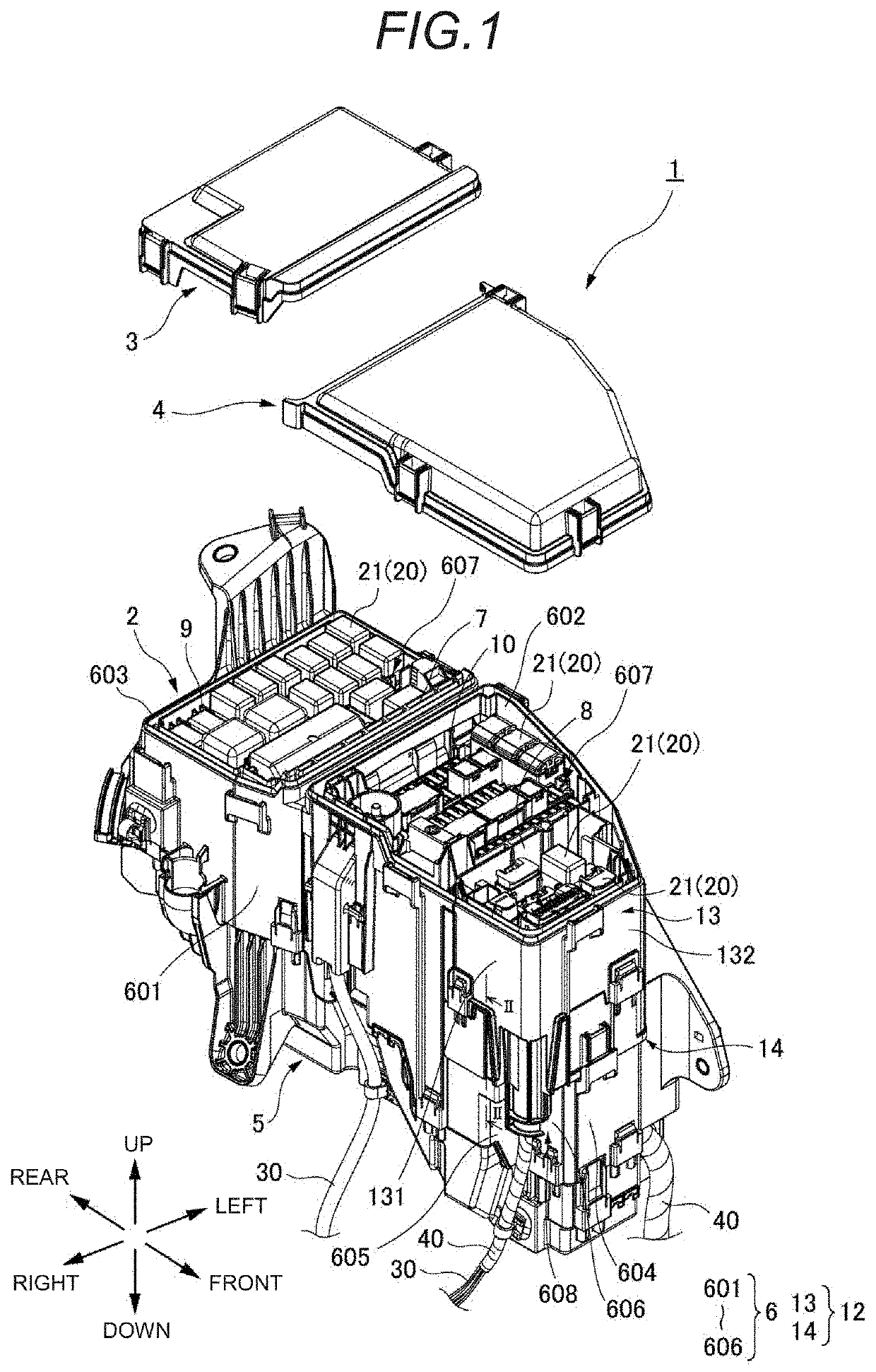
[0015]An electric junction box 1 according to the present embodiment is to be mounted on, for example, a vehicle, and is to be interposed between a power source (secondary battery) and an electronic device of a vehicle (not shown) to adjust electric power supplied from the power source to the electronic device. The electric junction box 1 may also be referred to as a relay box, a fuse box, a junction box, or the like.

[0016]As shown in FIG. 1, the electric junction box 1 according to the present embodiment accommodates electronic components 20 and electric wires 30 connected to the electronic components 20. The electric junction box 1 is to be disposed in an engine room provided on a front side of a vehicle. The electronic component 20 refers to a relay, a fuse, a fusible link, or the like. The electronic component 20 includes an electronic component body (not shown) such a...


PUM


Abstract

An electric junction box includes a fitting component to which an electronic component and an electric wire electrically connected to the electronic component are assembled, and a housing in which the fitting component is fitted and held. The fitting component includes a first peripheral wall forming an outer side face of the fitting component, a first bottom wall covering a lower opening of the first peripheral wall, a first drain hole provided in the first bottom wall, and a cylindrical drain portion protruding downward from an edge portion of the first drain hole in the first bottom wall.

Description

CROSS REFERENCE TO RELATED APPLICATIONS[0001]This application claims priority from Japanese Patent Application No. 2019-183613 filed on Oct. 4, 2019, the entire contents of which are incorporated herein by reference.BACKGROUND OF THE INVENTIONField of the Invention[0002]The present invention relates to an electric junction box such as a fuse box or a junction box.Description of Related Art[0003]An in-vehicle electric junction box, in which an electronic component such as a fuse or a relay is detachably mounted on a face thereof, is known (see Patent Literature 1: JP-A-2017-127078 and Patent Literature 2: JP-A-2015-56994). This type of electric junction box includes one in which a connector (fitting component), in which an electronic component and an electric wire are assembled, is placed on an electronic component accommodating chamber of a housing in a stack manner. It is conceivable to provide the connector with a bottom wall in order to protect the electric wire assembled to the ...

Claims


Application Information

Patent Timeline
Patent Type & Authority Patents(United States)
IPC IPC(8): H02G3/08
CPCH02G3/088H02G3/081H02G3/16B60R16/03B60R16/0238
Inventor KURATA, SHOKAWAMURA, HIDEKIUMEZAKI, MINORUKAMIYA, KENTAMASUDA, JUNYA
Owner YAZAKI CORP
Why Eureka
Try Eureka