Reinforced electrical terminal

a technology of electrical terminals and reinforced parts, which is applied in the direction of coupling contact members, coupling device connections, electrical apparatus, etc., can solve the problems of terminals being vulnerable to damage or deformation when in use, and achieve the effects of removing loose components, and preventing damage or deformation of retention parts

Active Publication Date: 2021-12-28
TYCO ELECTRONICS LOGISTICS AG (CH)
View PDF1 Cites 0 Cited by
  • Summary
  • Abstract
  • Description
  • Claims
  • Application Information

AI Technical Summary

Benefits of technology

[0004]It is another object of the subject invention to provide a one piece connector, thereby eliminating loose components which can fall during installation or which can come loose during operation.
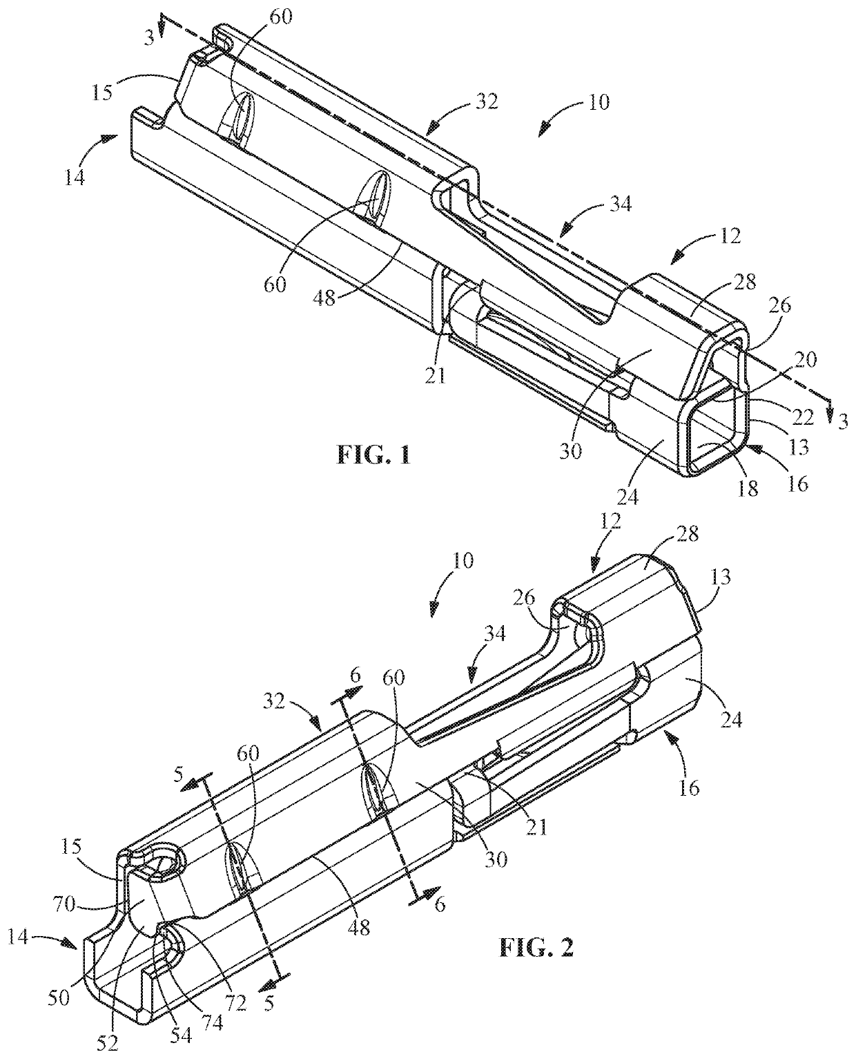
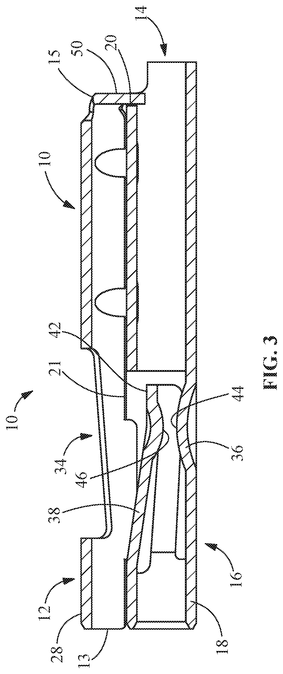
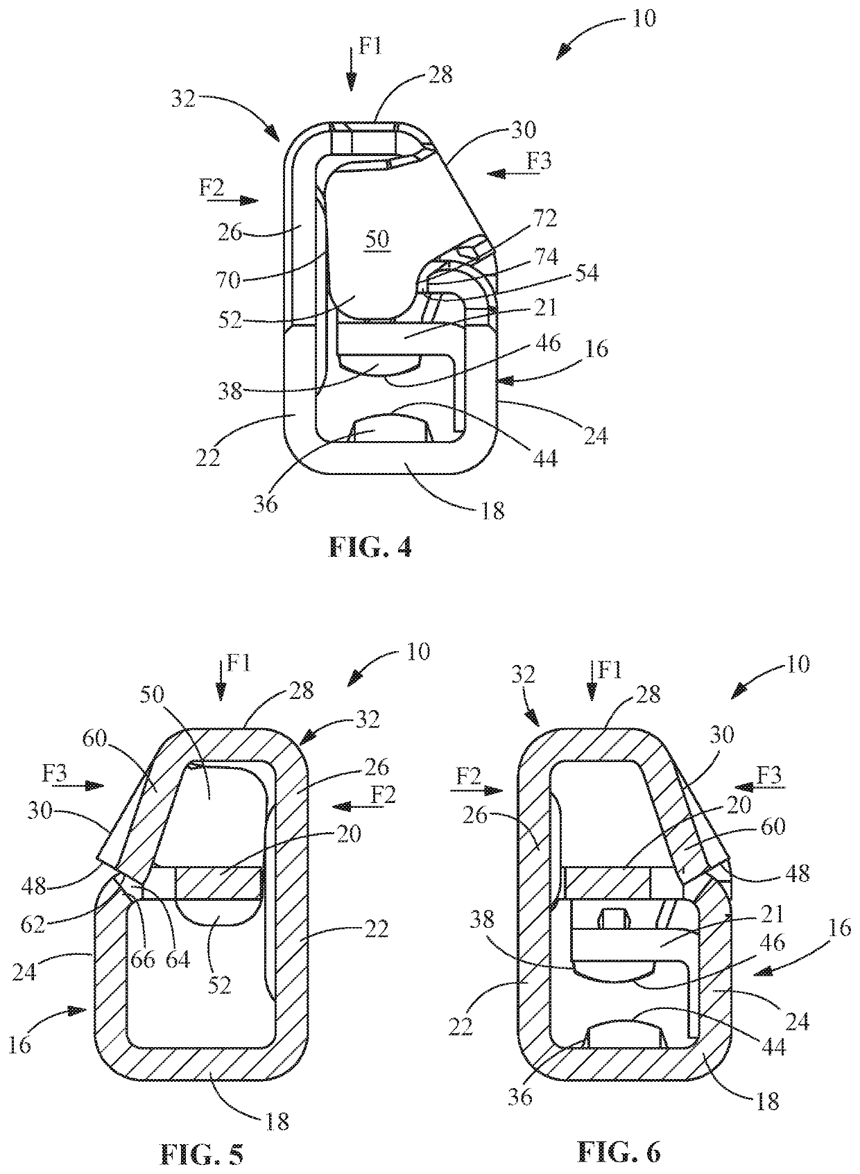
[0005]An embodiment is directed to an electrical contact a mating portion for mating with a mating contact. The mating portion has a contact portion and a retention portion. The mating portion has a mating portion bottom wall, a mating portion top wall and mating portion side walls. A respective mating portion side wall has an upper portion which extends beyond the top wall, the upper portion extends to form the retention portion. The retention portion has a retention portion top wall, a retention portion side wall and a retention portion back wall. The retention portion back wall is configured to approximate the space provided between the mating portion top wall, the upper portion of the respective mating portion side wall, the retention portion top wall and a retention portion side wall. The retention portion back wall cooperates with one or more of the mating portion top wall, the upper portion of the respective mating portion side wall, the retention portion top wall and a retention portion side wall to prevent damage or deformation of the retention portion as a force applied to the retention portion.
[0006]An embodiment is directed to an electrical contact a mating portion for mating with a mating contact. The mating portion has a contact portion and a retention portion. The mating portion has a mating portion bottom wall, a mating portion top wall and mating portion side walls. A respective mating portion side wall has an upper portion which extends beyond the top wall, the upper portion extends to form the retention portion. A detent receiving opening is provided on the mating portion top wall. The retention portion has a retention portion top wall and a retention portion side wall. A detent is provided on the retention portion side wall and extends from a free end of the retention portion side wall. the detent is positioned in alignment with the detent receiving opening. The detent cooperates with the detent receiving opening to prevent damage or deformation of the retention portion as a force applied to the retention portion.

Problems solved by technology

The miniaturization of the terminals requires that less material be used in the manufacturer of the terminals, thereby making the terminals vulnerable to damage or deformation when in use or when undergoing testing, qualification or assembly into the connector housing.

Method used


Image

  • Reinforced electrical terminal
  • Reinforced electrical terminal
  • Reinforced electrical terminal

Examples


Embodiment Construction

[0017]The description of illustrative embodiments according to principles of the present invention is intended to be read in connection with the accompanying drawings, which are to be considered part of the entire written description. In the description of embodiments of the invention disclosed herein, any reference to direction or orientation is merely intended for convenience of description and is not intended in any way to limit the scope of the present invention. Relative terms such as “lower,”“upper,”“horizontal,”“vertical,”“above,”“below,”“up,”“down,”“top” and “bottom” as well as derivative thereof (e.g., “horizontally,”“downwardly,”“upwardly,” etc.) should be construed to refer to the orientation as then described or as shown in the drawing under discussion. These relative terms are for convenience of description only and do not require that the apparatus be constructed or operated in a particular orientation unless explicitly indicated as such. Terms such as “attached,”“affi...


PUM


Abstract

An electrical contact a mating portion for mating with a mating contact. The mating portion has a contact portion and a retention portion. The mating portion has a mating portion bottom wall, a mating portion top wall and mating portion side walls. A respective mating portion side wall has an upper portion which extends beyond the top wall. The retention portion has a retention portion top wall, a retention portion side wall and a retention portion back wall. The retention portion back wall is configured to approximate the space provided between the mating portion top wall, the upper portion of the respective mating portion side wall, the retention portion top wall and a retention portion side wall. The retention portion back wall prevents damage or deformation of the retention portion as a force applied to the retention portion.

Description

FIELD OF THE INVENTION[0001]The present invention is directed to an electrical terminal with improved strength. In particular, the invention is directed to a terminal with improved strength to avoid damage when undergoing qualification or assembly into the connector housing.BACKGROUND OF THE INVENTION[0002]The need for electrical connectors which are compact in size continues to increase. As the connectors are made smaller, the electrical terminals positioned in the connectors must also be made smaller. The miniaturization of the terminals requires that less material be used in the manufacturer of the terminals, thereby making the terminals vulnerable to damage or deformation when in use or when undergoing testing, qualification or assembly into the connector housing.[0003]It would, therefore, be beneficial to provide a terminal with improved strength to prevent damage or deformation. It would also be beneficial to provide such a reinforced terminal without increasing the overall si...

Claims


Application Information

Patent Timeline
Patent Type & Authority Patents(United States)
IPC IPC(8): H01R13/434H01R13/11
CPCH01R13/434H01R13/11H01R13/111H01R13/4223H01R13/113H01R13/432
Inventor RAYBOLD, CHRISTOPHER RYANKINSEY, JR., FORREST IRVINGHETRICK, RYAN DAVIDMYER, JOHN MARK
Owner TYCO ELECTRONICS LOGISTICS AG (CH)
Why Eureka
Try Eureka