Ring sewing machine

A sewing machine and circular sewing technology, which is applied to sewing machine components, needle holders for sewing machines, and ferrule mechanisms for sewing machines, etc., can solve problems such as difficulty in completing threading operations.

Inactive Publication Date: 2009-09-30
JUKI CORP
View PDF0 Cites 13 Cited by
  • Summary
  • Abstract
  • Description
  • Claims
  • Application Information

AI Technical Summary

Problems solved by technology

[0006] Therefore, there is the following problem: after the looping thread is inserted into the inlet hole 102a, when the thread is drawn out from the outlet hole 102b, the sewing needle 101 becomes an obstacle and the threading operation is difficult to complete.

Method used


Image

  • Ring sewing machine
  • Ring sewing machine
  • Ring sewing machine

Examples


Deformed example 1

[0075] In addition, the present invention is not limited to the above-mentioned embodiment. For example Picture 9 As shown, the following tension applying device 60 can also be used, which can adjust the fixed position of at least one pulley 61a of the two pulleys 61a and 61b along the moving direction of the base 62. Specifically, on the base 62, a groove 62a is formed along the moving direction of the base 62. A guide pin 63 is erected on the bottom surface of the pulley 61a on one side. The guide pin 63 is formed to be inserted into the groove 62a, and a threaded groove is formed on the surface. A fastening member such as a nut 64 is fitted into the guide pin 63 from the back side of the base 62, and after adjusting the position of the guide pin 63 in the groove 62a, the position of the pulley 61a can be fixed by tightening with the nut 64. The mounting of the base 62 with respect to the cover 45 is to insert a guide pin 65 standing on the base 62 with a threaded groove formed...

Deformed example 2

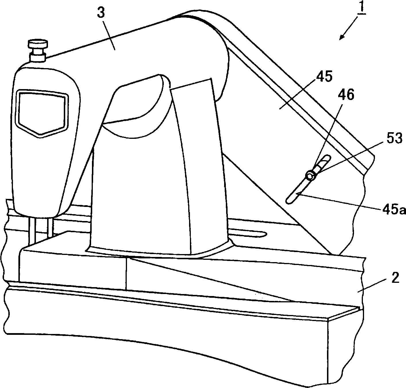
[0080] In addition, such as Picture 11 As shown, it is also possible to provide a stopper 70 at the initial position of the tension applying device 50 in the sewable state, which abuts against the aforementioned base 52 in the moving direction of the tension applying device 50. Specifically, in the state before the phases of the needle 17 and the looper 24 are shifted (the state where the pulley applies appropriate tension to the timing belt), a stopper 70 is provided on the outer cover 45, which is on the base The initial position of 52 abuts the base 52. The stopper 70 only needs to be present on the movement path of the base 52 that can move along the adjustment groove 45a, and it may be formed in any manner.

[0081] By adopting the above structure, after the base 52 is moved to move the looper 24 away from the needle 17 and the thread is threaded, when returning to the original sewable state, the user only needs to move the base 52 to abut the stopper 70 The location can be ...


PUM


Abstract

The invention provides a ring sewing machine which preventing loosening of looper, and enhancing workability of threading through looper in the mean time. The ring sewing machine comprises an upper shaft and a lower shaft which are disposed parallel to each other; a ring shaped synchronous belt, which is disposed between the upper shaft and the lower shaft and delivers rotation thereof to the lower shaft; a needle rod, which is connected to the upper shaft and swings cooperatively with the rotation of the upper shaft; and a looper shaft, which is connected to the lower shaft, and swings cooperatively with the rotation of the lower shaft. The ring sewing machine comprises a tension applying means including two belt wheels, which are arranged on external side of the synchronous belt with the synchronous belt clamped therein; and a substrate for supporting two belt wheels, which is capable of moving on the direction intersecting the line formed by connecting the upper shaft core and lower shaft core.

Description

Technical field [0001] The invention relates to a loop stitch sewing machine which forms loop stitches through the coordinated action of a sewing needle and a looper. Background technique [0002] Currently, the following ring stitch sewing machine is known, which has a looper that is freely swingable under the needle in the base of the sewing machine, so that the loop thread passing through the looper is wound toward the upper thread passing through the needle. Form a loop stitch. [0003] In the above-mentioned sewing machine, in order to form the loop stitch, it is necessary to hook the loop formed by the upper thread of the sewing needle by the looper. Therefore, it is necessary to accurately adjust the timing of the up and down movement of the needle and the swing of the looper before sewing. [0004] In addition, such as Figure 13 As shown, when the sewing machine is stopped and the looper 102 is inserted into the looper 102, it is necessary to insert the looper through th...

Claims


Application Information

Patent Timeline
Patent Type & Authority Applications(China)
IPC IPC(8): D05B57/00D05B57/30D05B63/00D05B55/14
Inventor 坂本真一新井富夫
Owner JUKI CORP
Why Eureka
Try Eureka