Quick connect power connector

Active Publication Date: 2015-01-29
TYCO ELECTRONICS LOGISTICS AG (CH)
View PDF5 Cites 12 Cited by
  • Summary
  • Abstract
  • Description
  • Claims
  • Application Information

AI Technical Summary

Benefits of technology

[0009]In view of the above, it is an object of the subject invention to provide a connector which provides a

Problems solved by technology

However, the threaded components of these prior art connectors are fairly expensive to manufacture.
Furthermore, the threaded interconnection adds significantly to assembly time and costs and can make disassembly for periodic repair and maintenance difficult, particularly as torque wrenches are required to properly seat the hardware.
A number of parts are required to perfect the electrical connection, thereby also adding to the cost of the connection and creating the possibility of foreign object debris (FOD) which could damage engines and the like.
Also, as the connectors are exposed to vibration and the like, the nuts may rotate off of the threaded component, which can lead to a failed, open electrical connection.
In addition, any attempt to provide environmental sealing for such an electrical connection will generally require an entirely separate protection means that is functionally and structurally unrelated to the threaded interconnection to the alternator.
However, it is extremely difficult to achieve the high contact forces with an electrical connector that must also ensure a large surface contact area and a large cross sectional

Method used


Image

  • Quick connect power connector
  • Quick connect power connector
  • Quick connect power connector

Examples


Example

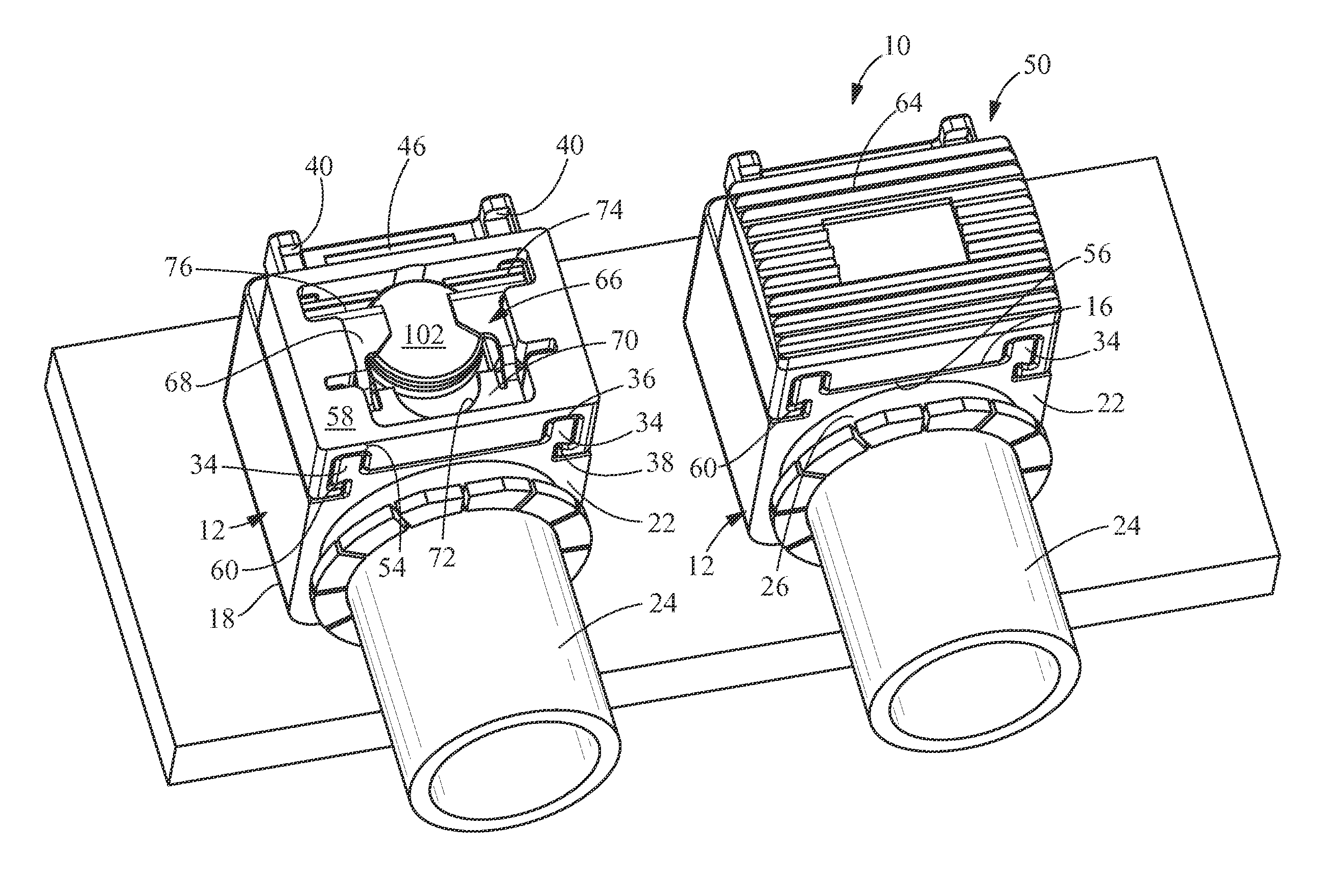
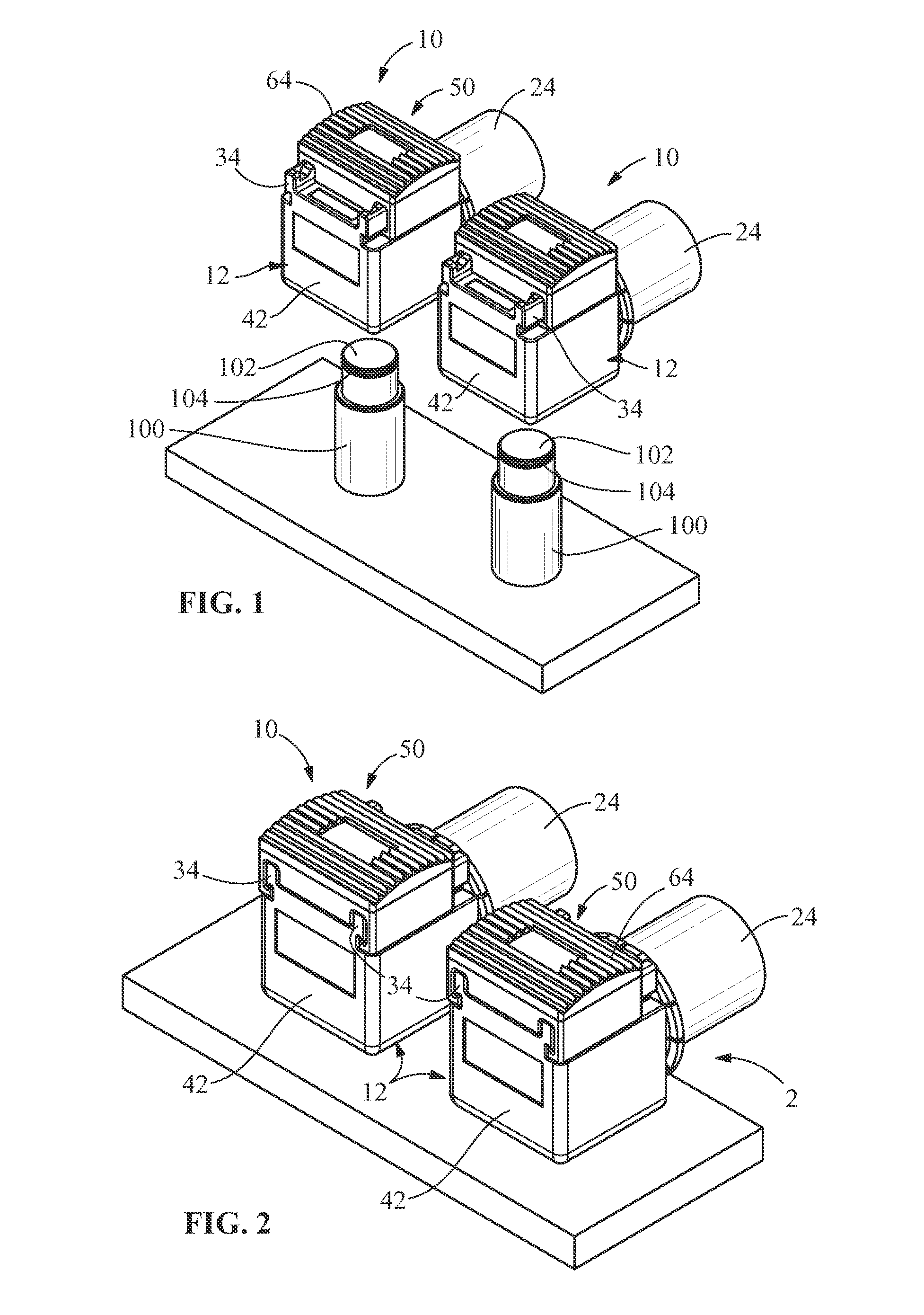
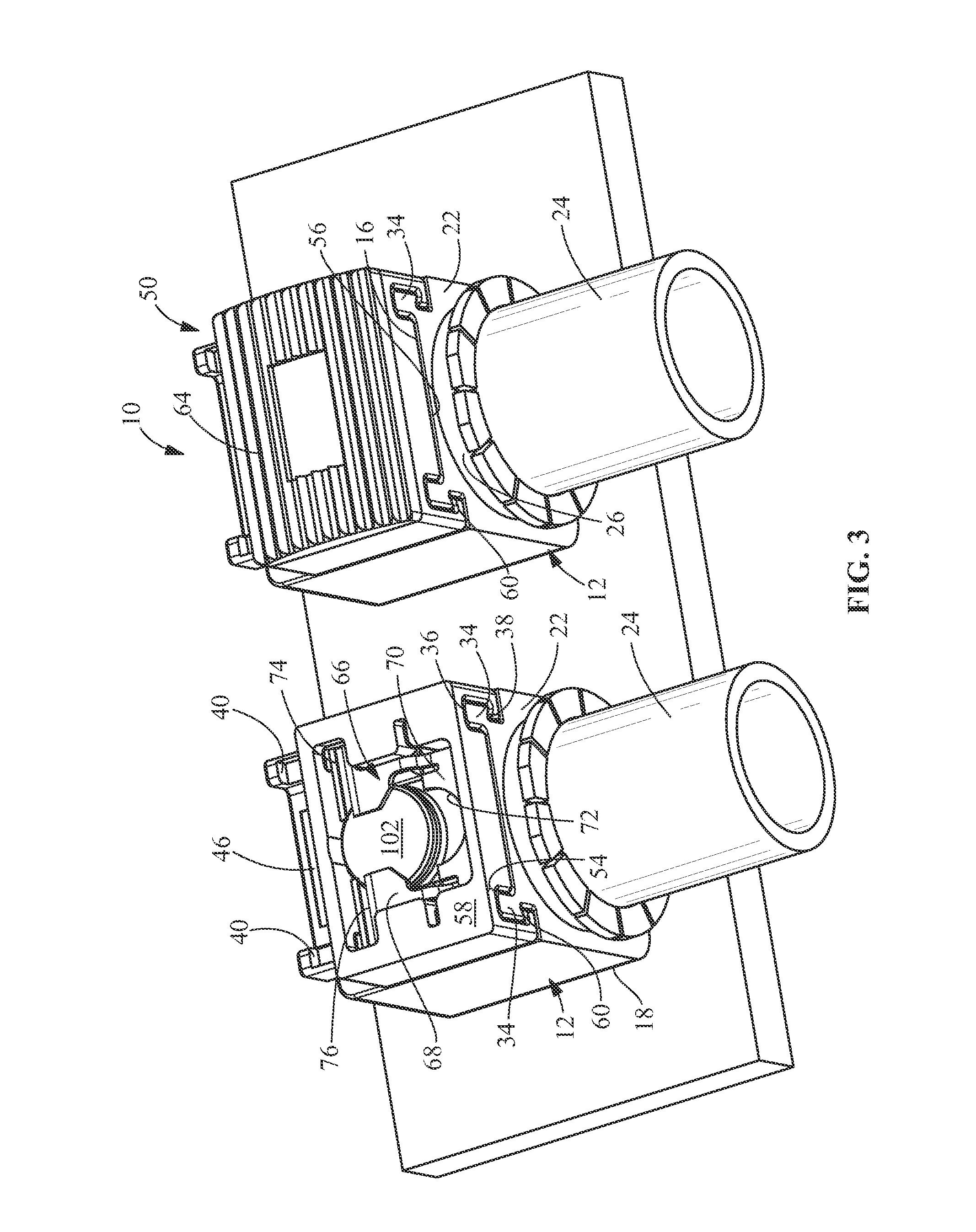
[0035]The description of illustrative embodiments according to principles of the present invention is intended to be read in connection with the accompanying drawings, which are to be considered part of the entire written description. In the description of embodiments of the invention disclosed herein, any reference to direction or orientation is merely intended for convenience of description and is not intended in any way to limit the scope of the present invention. Relative terms such as “lower,”“upper,”“horizontal,”“vertical,”“above,”“below,”“up,”“down,”“top” and “bottom” as well as derivative thereof (e.g., “horizontally,”“downwardly,”“upwardly,” etc.) should be construed to refer to the orientation as then described or as shown in the drawing under discussion. These relative terms are for convenience of description only and do not require that the apparatus be constructed or operated in a particular orientation unless explicitly indicated as such. Terms such as “attached,”“affi...


PUM


Abstract

An electrical connector for connecting to a terminal post. A contact is provided in electrical engagement with the terminal post regardless of the orientation of the contact with respect to the terminal post. A locking slide is moveably mounted to the housing body. A first reference member is provided on a first end of the body of the connector, the first reference member is provided proximate a first sidewall of the body of the connector. A second reference member is provided on the first end of the body of the connector, the second reference member is provided proximate a second sidewall of the body of the connector. When the locking slide is in the prelocked position, the first reference member is visible and when the locking slide is in the locked position, the second reference member is visible.

Description

FIELD OF THE INVENTION[0001]The present invention is directed to an electrical connector which provides a quick, simple and reliable connection to mating posts. In particular, the invention is directed to an electrical connector which prevents the improper mating of the connector to the post and provides a visual indication that the proper connection is secured.BACKGROUND OF THE INVENTION[0002]Electrical connectors for military, aviation, vehicular and other applications which required power must be able to withstand the environmental conditions, such as high vibrations, to which such connectors are subjected. The connectors also must provide high quality electrical connection through very broad ranges of temperature variations. Additionally, electrical connectors that are disposed in engine compartments and the like must protect against the inadvertent but inevitable manual contact that occurs as a mechanic tries to access a nearby component disposed in the crowded compartment. In ...

Claims


Application Information

Patent Timeline
IPC IPC(8): H01R13/641H01R13/627
CPCH01R13/6275H01R13/641H01R11/282H01R11/285H01R4/48H01R13/6271H01R13/639
Inventor OH, LAWRENCE SE-JUNMCKIBBEN, JOHN LOUISFABIAN, DAVID JAMESYI, CHONG HUNMULFINGER, ROBERTYOHN, BRENT DAVID
Owner TYCO ELECTRONICS LOGISTICS AG (CH)
Why Eureka
Try Eureka