Operator cab for construction machine

a technology for operating cabs and construction machines, which is applied to roofs, doors, wing accessories, etc., can solve the problems of the door in its opened condition exceeding the turning radius, and achieves the effects of high endurance, good door operation, and high water tightness

Active Publication Date: 2006-11-21
TAKEUCHI SEISAKUSHOKK +1
View PDF13 Cites 12 Cited by
  • Summary
  • Abstract
  • Description
  • Claims
  • Application Information

AI Technical Summary

Benefits of technology

[0011]By constructing the operator cab for a construction machine in a way as described above according to the present invention, a good feel of the door operation, i.e., the opening and closing of the door, is achieved because the movement of the door just before the complete closure is directed inward in a similar way as a prior-art hinged door. This inward movement of the door at the final moment of the closing pushes a seal member, which is provided to seal the door to the cab box, head-on, so the seal member achieves a high endurance and a high watertightness. Furthermore, the present invention provides an improved safety because the door never drops off from the cab box even if the slide member comes out of the slide rail accidentally, because the front part of the door is supported by the link members. Moreover, because the handle and the locks, which fix the door in its opened condition or in its closed condition, are provided in concentration at the front end of the door, the construction of the door is relatively simple. Therefore, the present invention achieves reductions in the weight of the door as well as in the manufacturing cost and enables the door to have a window at the central part of the door, the window widening the field of view from the inside of the operator cab.
[0012]Additionally, the link members, which comprise upper and lower link members at the upper and lower ends, respectively, of the door, contribute to the improvement in the feel of the door operation because this arrangement of the link members eliminates any looseness in the support of the front part of the door. Furthermore, as the lower link member is arranged never to enter the cab room, the safety and convenience of the operator getting into and out of the operator cab are not jeopardized. Moreover, the positioning of the slide rail approximately at the vertical center facilitates the smoothness of the door operation.
[0013]According to the present invention, the part of the side of the cab box that includes the door extends linearly in a top view. This design enables to provide relatively large widths for the front and the rear of the operator cab and thereby secures a wider space especially at the feet of the operator in the cab room.

Problems solved by technology

However, in a case of a small construction machine, as the turning radius is accordingly small, there is a probability that the door in its opened condition exceed the turning radius.

Method used


Image

  • Operator cab for construction machine
  • Operator cab for construction machine
  • Operator cab for construction machine

Examples


first embodiment

(First Embodiment)

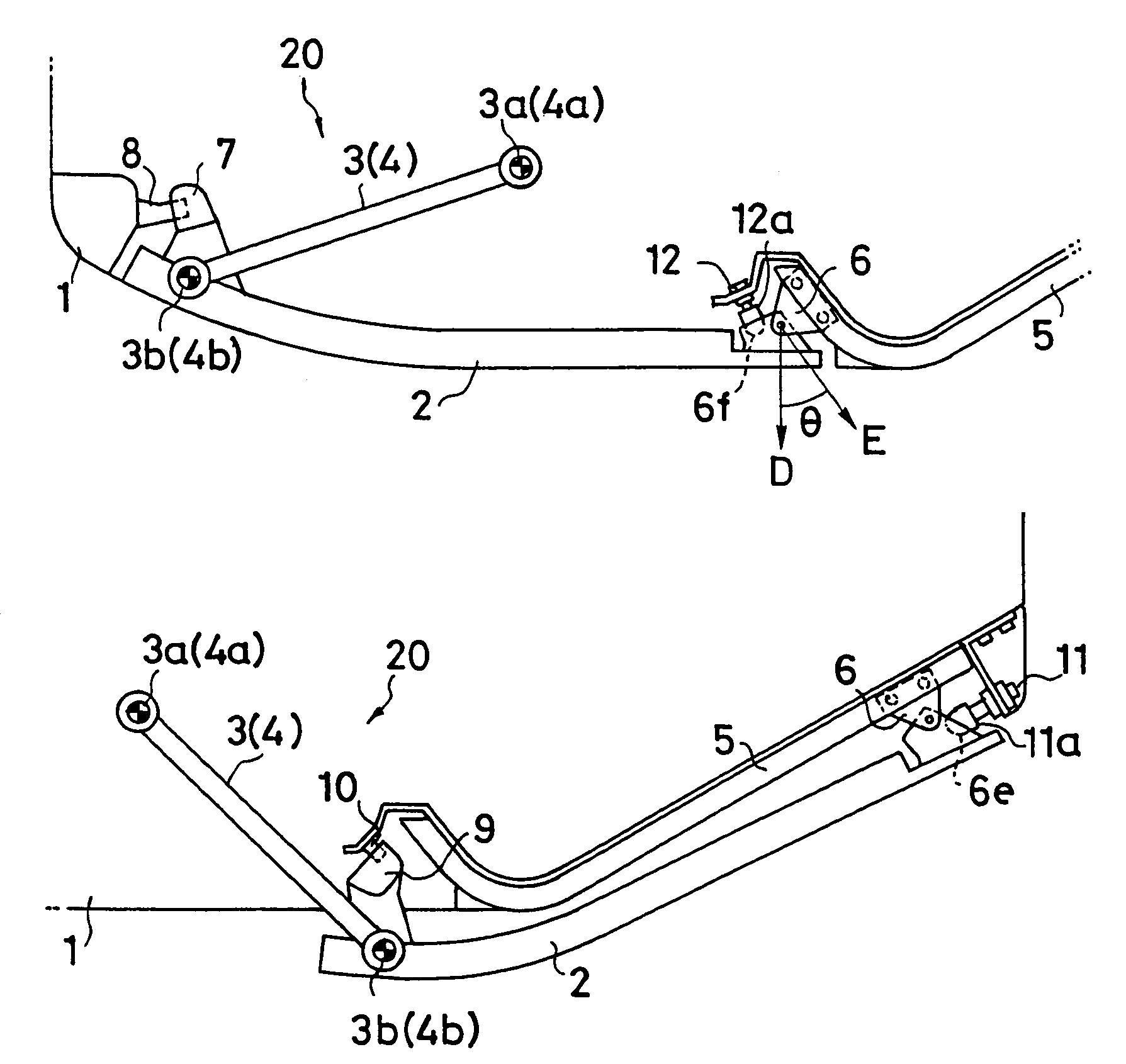
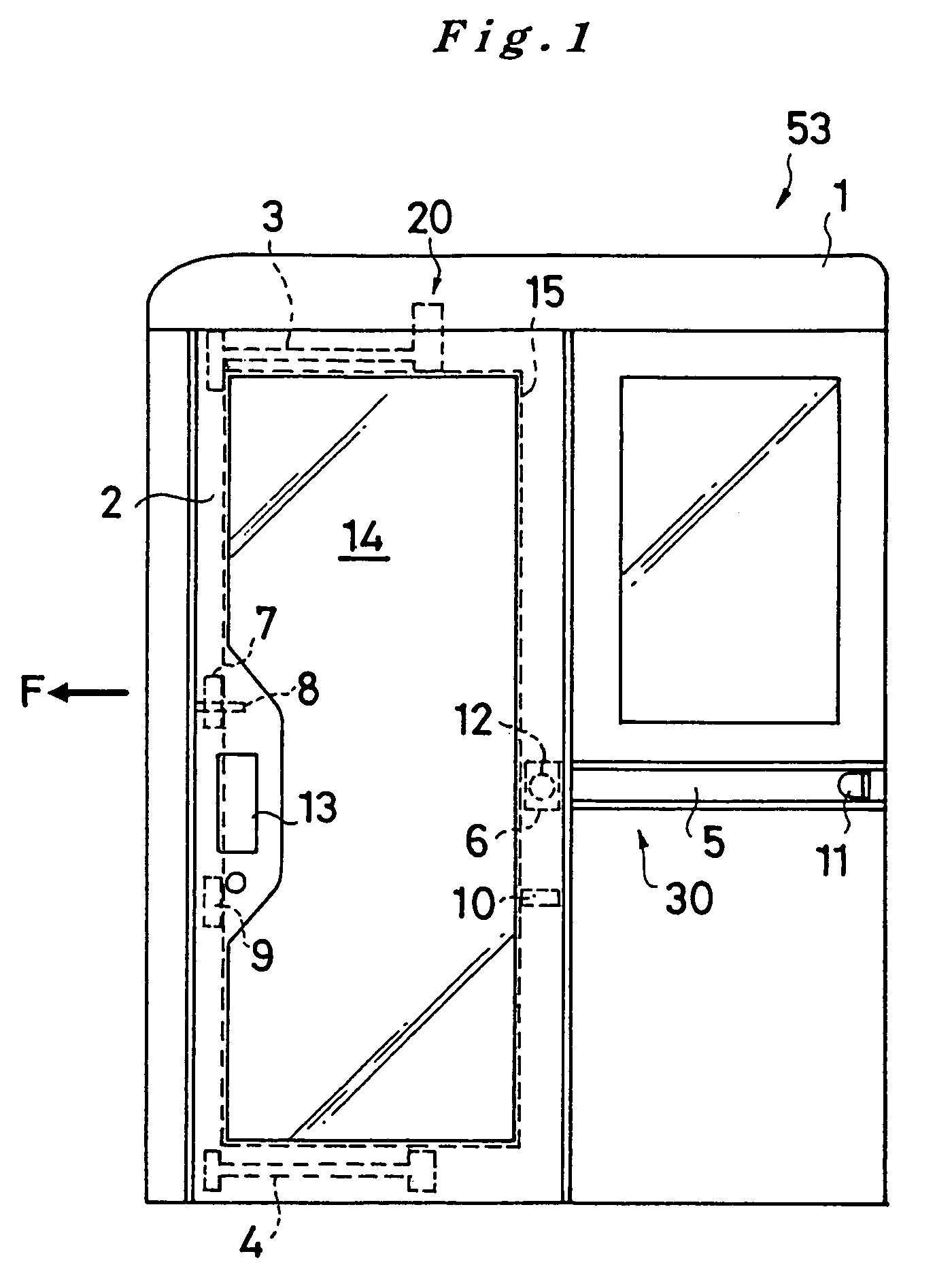
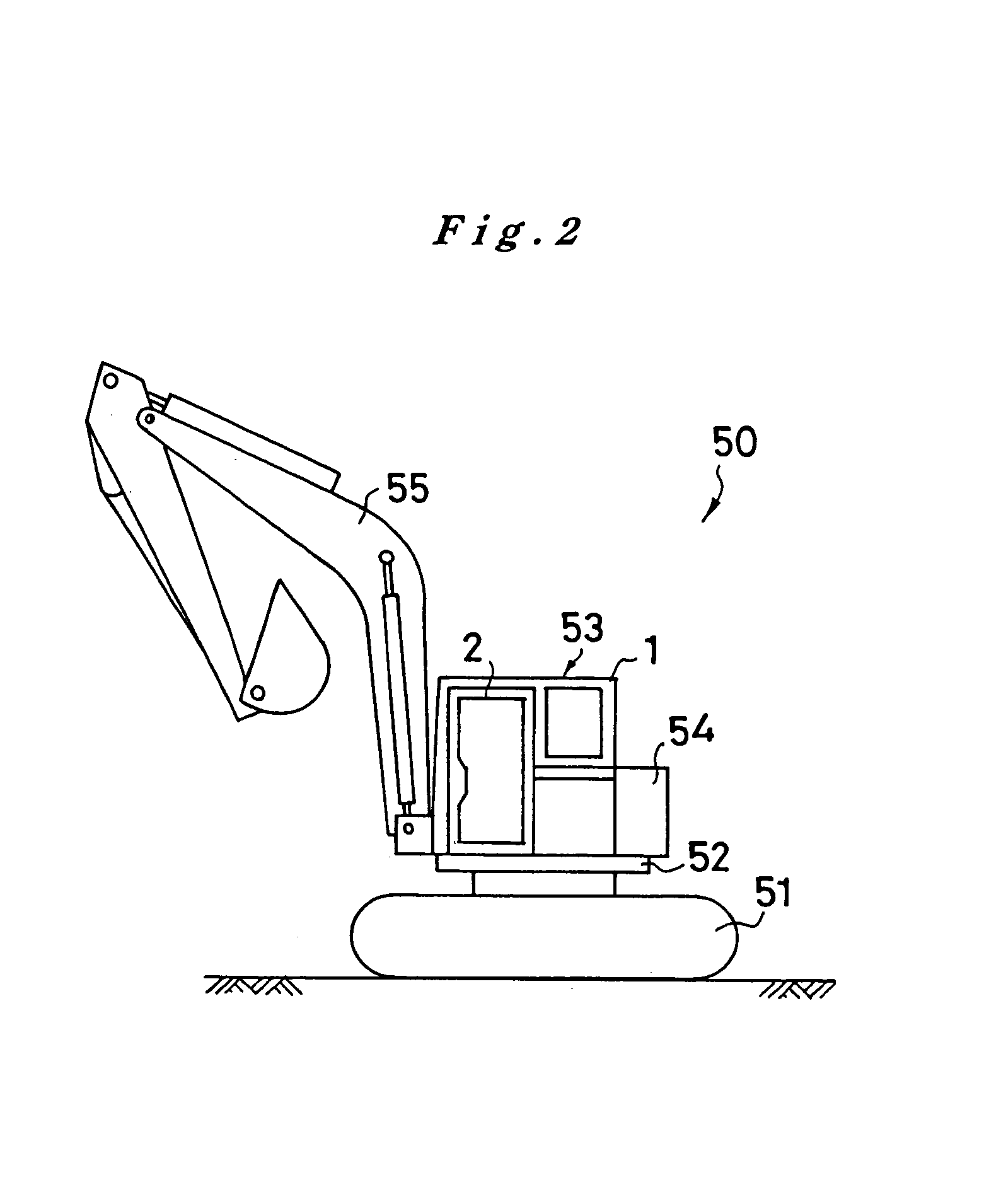
[0033]Now, the construction of a door 2 as a first embodiment, which is attached to the operator cab 53, is described in reference to FIG. 1˜FIG. 8. In the following description, the direction of the closing of the door is referred to as “forward” (arrow F in FIG. 1). As shown in FIG. 1, the door 2, whose front side is attached to the cab box 1 by a link mechanism 20 and whose rear side is attached to the cab box 1 by a slide mechanism 30, opens and closes an entrance 15 to the cab room 1a, which is defined by the cab box 1. The link mechanism 20 comprises an upper link member 3, which is located at the upper part of the door 2, and a lower link member 4, which is located at the lower part of the door 2. One end of each link member is connected pivotally to the cab box 1, and the other end is connected pivotally to the door 2, so that the link members can swing freely. On the other hand, the slide mechanism 30, which is positioned approximately at the vertical cent...

second embodiment

(Second Embodiment)

[0050]In the first embodiment, the front part of the door 2 is supported by the link mechanism 20 while the rear part is supported by the slide mechanism 30. However, it is possible that both the front and rear of the door be supported either by a link mechanism or by a slide mechanism alone, so each of such cases is described in the following, where components identical to those of the first embodiment are indicated by the same numerals to leave out redundant explanation.

[0051]At first, as a second embodiment, a case where both the front and rear parts of the door 2 are supported by a link mechanism 120 is described in reference to FIG. 11˜FIG. 13. The link mechanism 120 in the second embodiment comprises a front link member 103 and a rear link member 104, which are positioned, respectively, one in front of the other. One end (fixed end 103a or 104a) of each link member is connected pivotally to the cab box 1 at the upper part thereof, and the other end (moving e...

third embodiment

(Third Embodiment)

[0056]As a third embodiment, a case where both the front and rear parts of the door 2 are supported only by slide mechanisms 30, 230 and 240 is described in reference to FIG. 14˜FIG. 16. In the third embodiment, the upper front part of the door 2 is supported by the upper slide mechanism 230, the lower front part of the door 2 is supported by the lower slide mechanism 240, and the approximate, vertical center of the rear part of the door 2 is supported by the slide mechanism 30, which is the same as the first embodiment.

[0057]The upper slide mechanism 230 comprises an upper slide rail 203, which is attached on the cab box 1 along the upper side of the entrance of the cab box 1, and an upper slide member 303, which slides along the upper slide rail 203. The lower slide mechanism 240 comprises a lower slide rail 204, which is attached on the cab box 1 along the lower side of the entrance, and a lower slide member 304, which slides along the lower slide rail 204.

[0058...


PUM


Abstract

An operator cab 53, which is mounted rotatable on the vehicle body 51 of a hydraulic mini-shovel 50, comprises a cab box 1, a door 2, upper and lower link members 3 and 4, a slide member 6, a closed door lock 7, an opened door lock 9 and a handle 13. The cab box 1 has an internal cab room 1a and an entrance 15, which leads into the cab room 1a. The door 2 closes and opens the entrance 15 when it is moved forward and rearward, respectively. The upper and lower link members 3 and 4 have fixed ends 3a and 4a, each of which is connected pivotally to the cab box 1, and moving ends 3b and 4b, each of which is connected pivotally to the front end of the door 2. The slide member 6 is connected pivotally to the rear end of the door 2 so as to swing freely and slides along a slide rail 5, which is provided externally on the cab box 1. The closed door lock 7, which is provided at the front end of the door 2, engages with a closed door striker 8, which is provided on the cab box 1, when the door 2 is closed. The opened door lock 9, which is provided at the front end of the door 2, engages with an opened door striker 10, which is provided on the cab box 1, when the door 2 is opened. The handle 13 is provided at the front end of the door 2 and interlocked with the closed door lock 7 and the opened door lock 9.

Description

FIELD OF THE INVENTION[0001]The present invention relates generally to an operator cab used for a construction machine and particularly to an operator cab for a construction machine which has an entrance door.BACKGROUND OF THE INVENTION[0002]Construction equipment such as a hydraulic mini-shovel comprises an operator cab and a construction machine, which are provided on a vehicle body, so that they are easily turned around for performing construction work. While work is being performed, the door of the operator cab, through which an operator gets into or out of the cab, is usually closed, but it is sometimes kept open. FIG. 10 shows a large construction machine 60. It comprises a turret 62, which is provided rotatable on a vehicle body 61, and an operator cab 63, which is mounted on the turret 62. In a case like this large construction machine 60, the turning radius R′ of the turret 62 is relatively large, so the door 64 of the cab 63 never exceeds the turning radius R′ even in its ...

Claims


Application Information

Patent Timeline
Patent Type & Authority Patents(United States)
IPC IPC(8): B62D33/06B60J5/00E02F9/16E05D15/10E05D15/30
CPCB60J5/0487E02F9/163E05D15/1005E05Y2900/518
Inventor NAKAYAMA, SHINICHISHINSEN, MITSUHISA
Owner TAKEUCHI SEISAKUSHOKK
Why Eureka
Try Eureka