
Apparatus for and method of creating a super hypermobile, super magnetic joint

a super magnetic joint and apparatus technology, applied in free standing, lighting and heating apparatus, support devices, etc., can solve the problems of limited flexibility and adjustability of the positioning of the lamp, affecting the flexibility of the position, and limiting the flexibility and adjustability of the position of the components, so as to achieve more flexibility in assembly and assembly.

Active Publication Date: 2022-01-11
SIMMONS SR DENNIS C
View PDF10 Cites 3 Cited by
  • Summary
  • Abstract
  • Description
  • Claims
  • Application Information

AI Technical Summary

Benefits of technology

The invention improves the flexibility and adjustability of positioning an embodiment or its components. It also provides a method for intelligent linking of components for more flexibility in assembly.

Problems solved by technology

This is severely limiting in the adjustability and flexibility of the positioning of the lamp if an obstacle lies in the path of any of the components of the embodiment.
In addition, the links / arms of the lamp will collide with each other while moving up or down on the y axis; left and right on the x axis, or back and forth on the z axis, impeding their flexibility in position.
If anything lies in the path of any of the components of the embodiment in FIG. 1, the flexibility and adjustability of the location of the components are limited.

Method used


Image

  • Apparatus for and method of creating a super hypermobile, super magnetic joint
  • Apparatus for and method of creating a super hypermobile, super magnetic joint
  • Apparatus for and method of creating a super hypermobile, super magnetic joint

Examples


examples

[0191]In the following examples, ferromagnetic elements are considered to be neodymium, samarium cobalt, iron nitride, or that of magnets with extremely hi coercivity and ability to generate and retain extremely high magnetic fields.

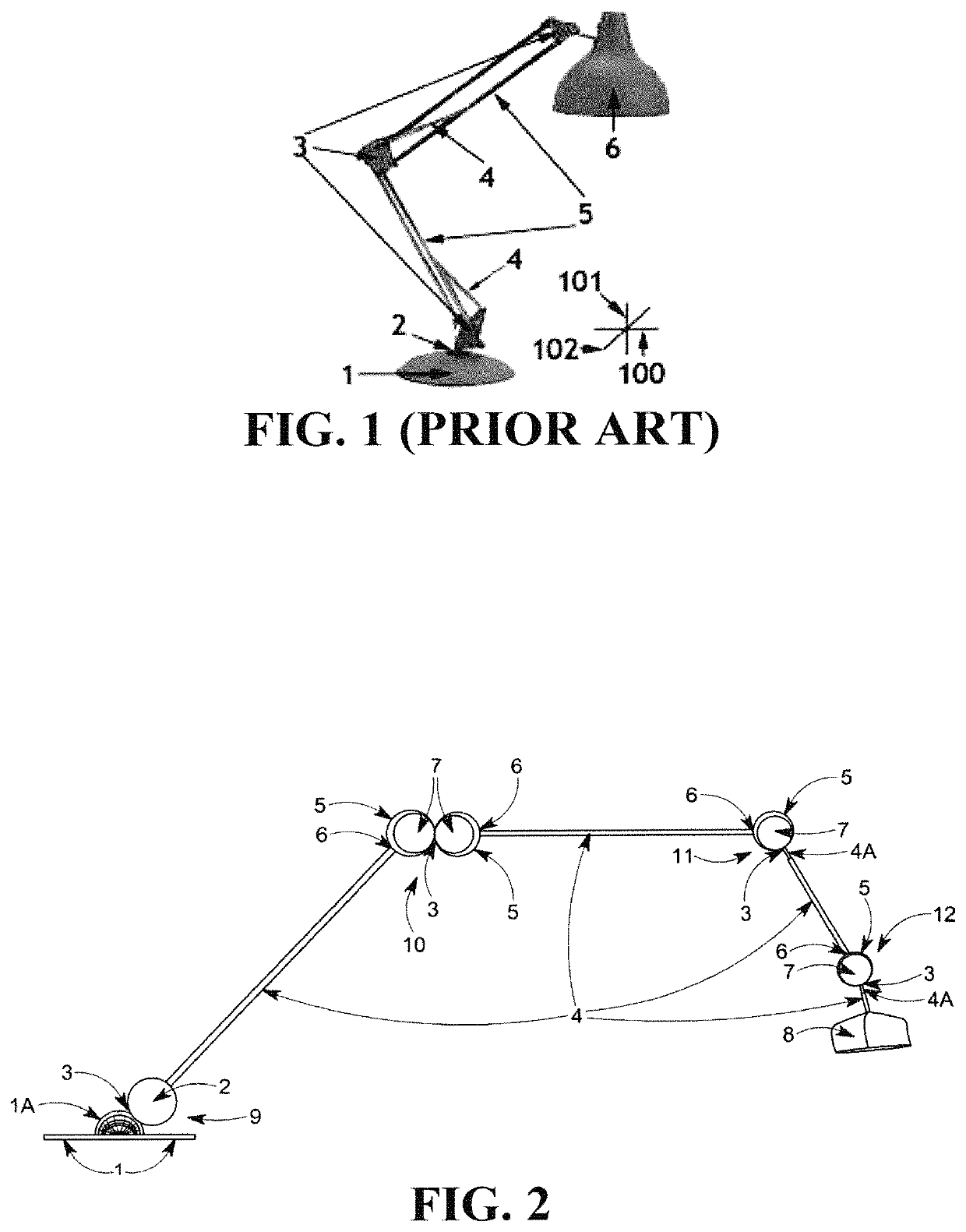
[0192]FIG. 2 shows an example embodiment with a hypermobile magnetic joint FIG. 2 (9); a super hypermobile, super magnetic joint FIG. 2 (10); and two hypermobile, super magnetic joints FIG. 2 (11) and FIG. 2 (12).

[0193]The base magnetic joint referenced by FIG. 2(9) in FIG. 2 is created by two separate ferromagnetic elements (FIG. 2 (1A) and FIG. 2 (2)) being magnetically attached / attracted to each other, but only ferromagnetic element FIG. 2 (2) is permanently magnetized. This means the joint is not a super magnetic joint.

[0194]If the base ferromagnetic element FIG. 2 (1A) was also permanently magnetized, its magnetic poles would be fixed, and the joint would then be a super magnetic joint. But permanently magnetized ferromagnetic element FIG. 2 (2) wou...


PUM

PropertyMeasurementUnit
magnetic domainsaaaaaaaaaa
magnetic fieldaaaaaaaaaa
magneticaaaaaaaaaa

Abstract

Disclosed are methods and apparatuses for creating hypermobile joints; hypermobile magnetic joints; super hypermobile joints; and super hypermobile, super magnetic joints. Joints can be simple magnetic, where one ferromagnetic element is a permanent magnet and the other is not; or super magnetic, where both are permanent magnets. Super hypermobile magnetic joints are created with two enclosures, joined magnetically and free to rotate around the other, with ferromagnetic elements inside the enclosures magnetized. As the moments of the magnetic domains of the enclosed magnetized ferromagnetic elements align parallel to each other inside each enclosure, as well as to the moments of the magnetic domains of the other magnetized ferromagnetic elements inside the other enclosure, the resulting magnetic attraction / attachment brings the enclosures together completing the joint. The frictional forces on the surfaces of the enclosures maintains the positions of the enclosures, and thus the joint.

Description

CROSS-REFERENCE TO RELATED APPLICATION[0001]Not ApplicableFIELD OF THE DISCLOSURE[0002]The present disclosure relates to a device / apparatus creating a super hypermobile, super magnetic joint, by allowing enclosures of the joint to rotate freely around the other; with all ferromagnetic elements inside the enclosures magnetized; the moments of the magnetic domains of the magnetized ferromagnetic elements aligned parallel to each other inside each enclosure, as well as to the moments of magnetic domains of magnetized ferromagnetic elements of the other enclosure; and the resulting magnetic attraction / attachment creating forces on the surfaces of the enclosures creating the joint.[0003]The present disclosure further relates to enabling a device / apparatus using the force of friction created from the attraction of multiple ferromagnetic elements on opposite sides of a steady / fixed surface, magnetically attracted / attached to each other, with at least one of the ferromagnetic elements magne...

Claims


Application Information

Patent Timeline
Patent Type & Authority Patents(United States)
IPC IPC(8): F16C11/06F16C11/04F16B1/00F21V21/29
CPCF16C11/04F16B1/00F16B2001/0035F21V21/29F21S6/003F21V21/28F21V17/105F16B2200/83
Inventor SIMMONS, SR., DENNIS C
Owner SIMMONS SR DENNIS C
Learn More