Apparatus for securing a patient in the trendelenburg position during surgery

a trendelenburg position and patient technology, applied in the field of trendelenburg position apparatus for securing patients during surgery, can solve the problems of compounding risks, limiting the ease of movement of patients to optimal surgical position, and inconvenient use of existing systems, so as to facilitate standardization of care, improve clinical efficacy, and improve the effect of time, staff utilization and safety for both patients

Active Publication Date: 2022-01-18
GOMEZ DAVID J
View PDF5 Cites 0 Cited by
  • Summary
  • Abstract
  • Description
  • Claims
  • Application Information

AI Technical Summary

Benefits of technology

[0007]The apparatus of the present invention improves and optimizes clinical efficacy, time, staff utilization, and safety for both patients and staff. The pad system facilitates standardization of care by creating less variance during use, while serving to improve safety for providers during ergonomic weight bearing physical movements routinely required during surgical positioning.
[0008]The apparatus of the present invention provides a standard approach to moving patients during routine and well known surgical procedures requiring positioning changes while securing the patient by means of a unique material reinforced viscoelastic pad using a non-residue pressure sensitive adhesive (“PSA”) system

Problems solved by technology

These risks are compounded with each increase in the angle of the Trendelenburg position.
One problem with existing pad or gel based systems is that once they are secured to bed rails, the existing systems are not easily moveable, especially when under the weight of the patient.
This limits ease of movement of the patient to an optimal surgical position once the patient is settled into the pad system and secured.
Due to the lack of easy and ergonomic movement of patients placed upon these fixed surfaces, providers are routinely forced to place the patient in a less than optimal position for anesthesia airway access needed for direct laryngoscopy, a necessary requirement for general anesthesia.
The draw sheet included in many viscoelastic foam packs is made of a paper/cloth like material and often lacks full strength to facilitate movement of the patient by providers when positioning changes are required.
This foam or gel bundling can lead to pr

Method used


Image

  • Apparatus for securing a patient in the trendelenburg position during surgery
  • Apparatus for securing a patient in the trendelenburg position during surgery
  • Apparatus for securing a patient in the trendelenburg position during surgery

Examples


Embodiment Construction

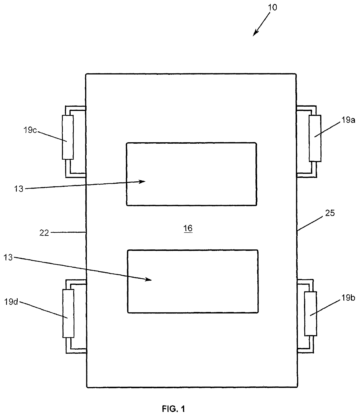
[0019]At the outset, it should be clearly understood that like reference numerals are intended to identify the same structural elements, portions or surfaces consistently throughout the several drawing figures, as such elements, portions or surfaces may be further described or explained by the entire written specification, of which this detailed description is an integral part. Unless otherwise indicated, the drawings are intended to be read (e.g., cross-hatching, arrangement of parts, proportion, debris, etc.) together with the specification, and are to be considered a portion of the entire written description of this invention. As used in the following description, the terms “horizontal”, “vertical”, “left”, “right”, “up” and “down”, as well as adjectival and adverbial derivatives thereof, (e.g., “horizontally”, “rightwardly”, “upwardly”, etc.), simply refer to the orientation of the illustrated structure as the particular drawing figure faces the reader. Similarly, the terms “inw...


PUM


Abstract

The apparatus of the present invention provides an apparatus for moving a patient on a pad and holding the pad in place on the surgical table. The disposable pad works in conjunction with the reusable patient lifting/moving base, allowing nurses to more readily and easily move patients on the table in order to facilitate surgical positioning. In another embodiment, the entire apparatus may be disposable. A pressure sensitive adhesive may hold the pad in place and prevent slippage between the pad and the top of the surgical table.

Description

CROSS-REFERENCE TO RELATED APPLICATION[0001]The present application is a divisional of U.S. patent application Ser. No. 14 / 437,017 filed on Feb. 20, 2017, entitled “Apparatus for Securing a Patient in the Trendelenburg Position During Surgery” which claims priority benefit of U.S. Provisional Patent Application No. 62 / 296,863 filed on Feb. 18, 2016, entitled “Method and Apparatus for Securing a Patient in the Trendelenburg Position During Surgery” and U.S. Provisional Patent Application No. 62 / 409,578 filed on Oct. 18, 2016, entitled “Method and Apparatus for Securing a Patient in the Trendelenburg Position During Surgery,” all of which are hereby incorporated by reference.TECHNICAL FIELD[0002]The present invention relates generally to the field of medical devices for use in the surgical theater, and more particularly to an apparatus for securing a patient in the Trendelenburg position and a method of using such an apparatus to move patients more ergonomically to facilitate a surgic...

Claims


Application Information

Patent Timeline
IPC IPC(8): A61G13/12A61G7/10
CPCA61G7/1023A61G7/1026A61G7/1073A61G13/1295A61G2210/90
Inventor GOMEZ, DAVID J.
Owner GOMEZ DAVID J
Why Eureka
Try Eureka