
Shaft hoisting plant having an overwind brake device

a technology of overwind brake and hoisting plant, which is applied in the direction of elevators, transportation and packaging, etc., can solve the problems of having to replace the plates destroyed by the hoisting machine in the process, and achieve the effect of low structural complexity and high follow-up costs

Active Publication Date: 2022-01-18
OLKO MASCHENTECHN
View PDF9 Cites 0 Cited by
  • Summary
  • Abstract
  • Description
  • Claims
  • Application Information

AI Technical Summary

Benefits of technology

The present invention aims to provide an overwind brake device that has low structural complexity and minimizes the risk of accidents. This device can help to avoid high costs in case of accidents.

Problems solved by technology

If the conveyance accidentally travels into the overwind brake device only along a part-length of the braking path, only the plates destroyed by the plow in the process have to be replaced.

Method used


Image

  • Shaft hoisting plant having an overwind brake device
  • Shaft hoisting plant having an overwind brake device
  • Shaft hoisting plant having an overwind brake device

Examples


Embodiment Construction

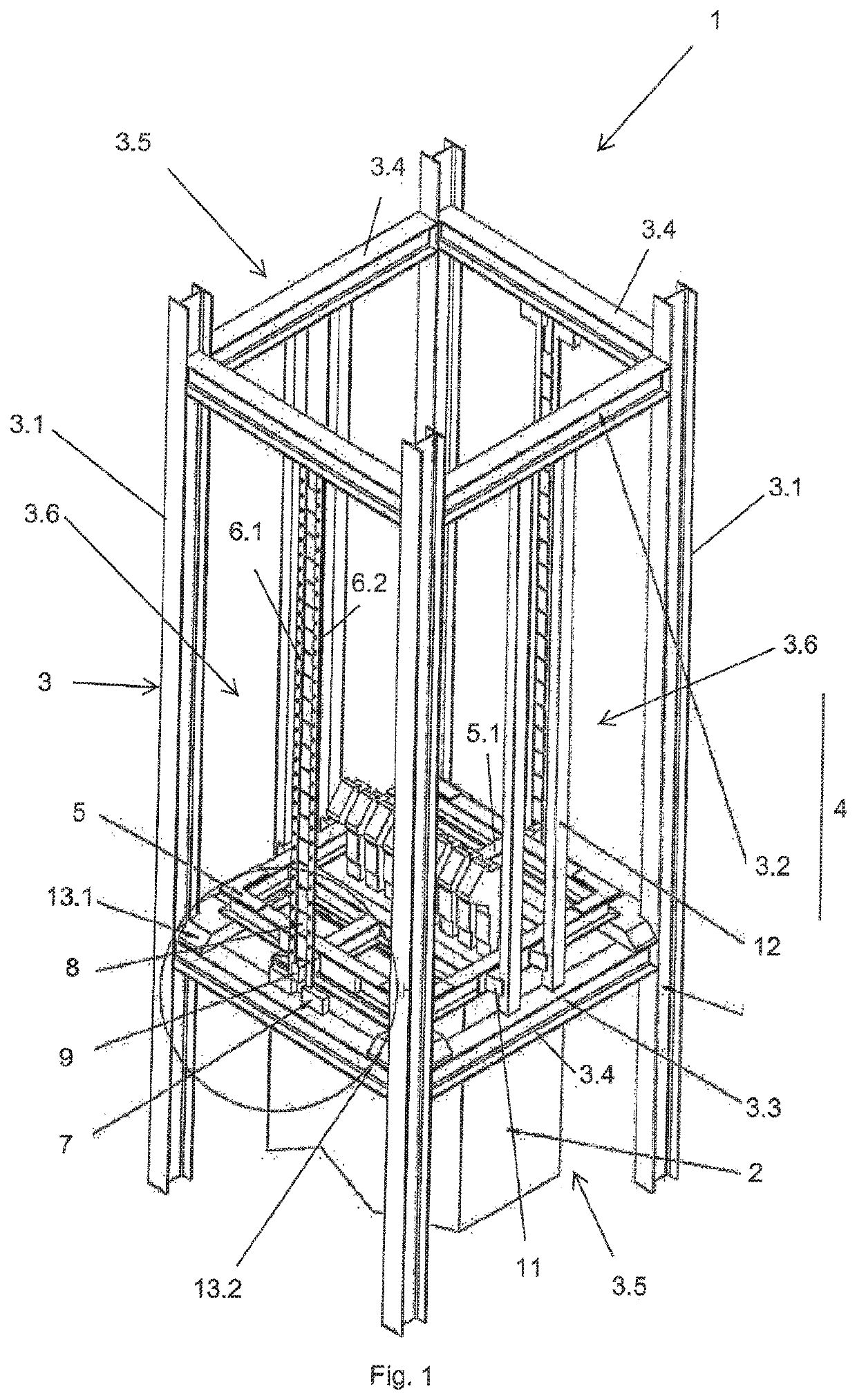
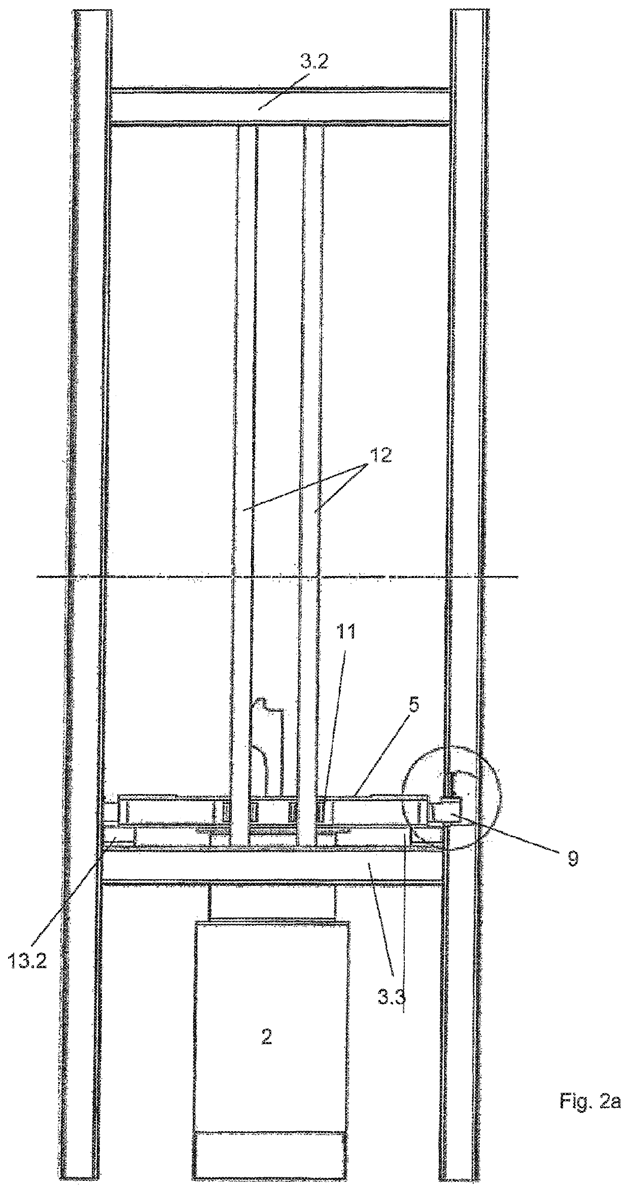
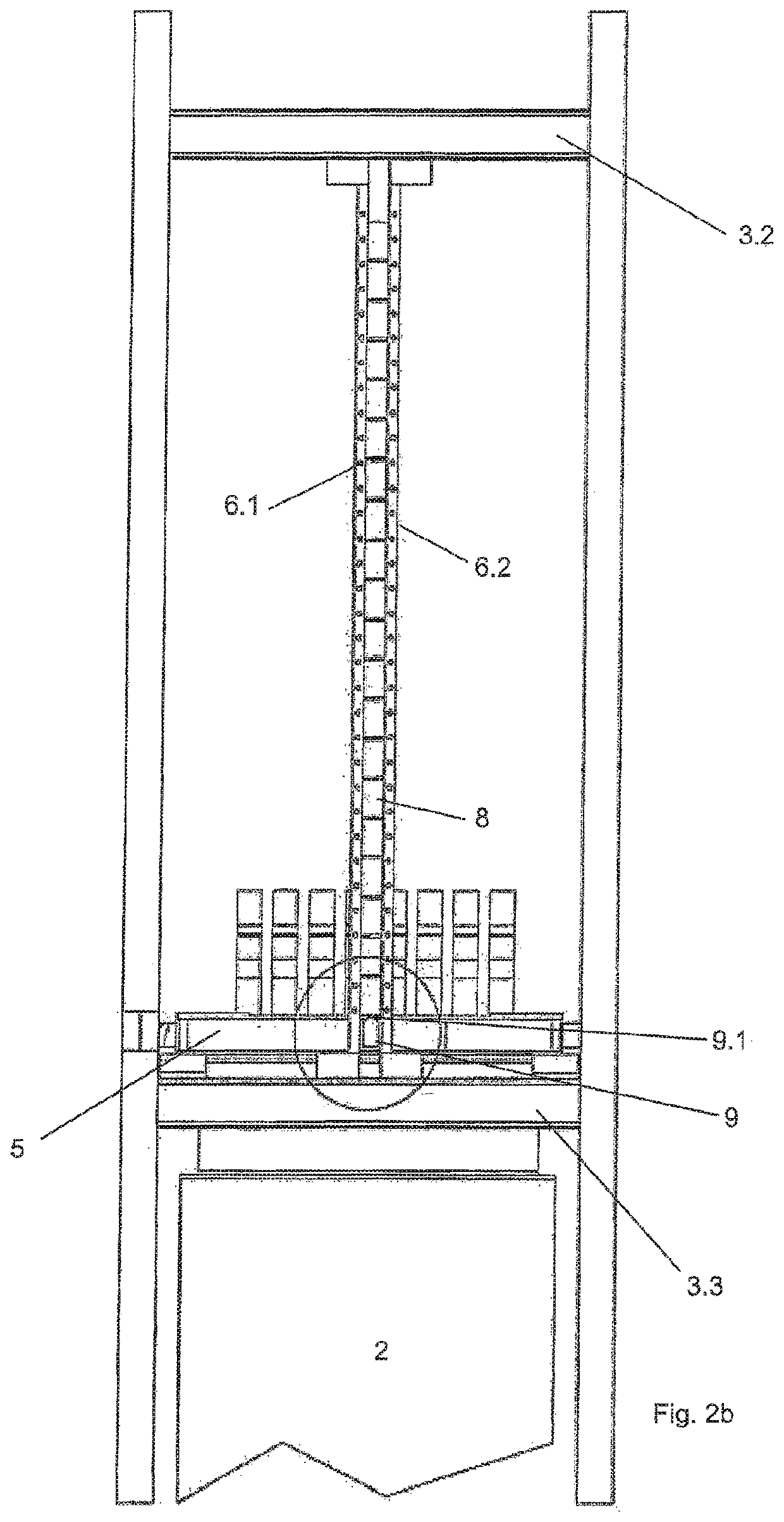
[0040]FIG. 1 shows a first exemplary embodiment of an overwind brake device (1) for a conveyance (2), configured as a cage, which is arranged at the end of the winding path above the upper filling station.

[0041]The overwind brake device (1) has a braking frame (5) which is positively driven in a longitudinal direction (4) in a guide framework (3), said braking frame (5) being set up to be struck by the conveyance (2) upon overwinding of the conveyance (2).

[0042]The guide framework (3) comprises four vertical support girders (3.1) and an upper brace (3.2) and a lower brace (3.3), which each consist of four cross girders (3.4) arranged between the support girders (3.1). The cuboidal guide framework (3) is bounded by opposite end sides (3.5) parallel to the open end sides of the cage (2), and opposite long sides (3.6) parallel to the side walls of the cage (2).

[0043]On the opposite long sides (3.6) of the guide framework (3), in each case one pair of retaining bars (6.1, 6.2) is fasten...


PUM


Abstract

A shaft hoisting plant has a conveyance and an overwind brake device for the conveyance, a travel path for the conveyance, and an overwind path adjoining a lower and / or upper end of the travel path. The overwind brake device includes retaining bars arranged in pairs in a manner spaced apart from one another and extending in a longitudinal direction, energy-absorbing material arranged in the form of plates arranged one above another in the longitudinal direction between the retaining bars. A plow is movable relative to the retaining elements, such that, upon overwinding of the conveyance, the plow deforms and / or destroys the energy-absorbing material between the retaining elements.

Description

CROSS-REFERENCE TO RELATED APPLICATIONS[0001]This application is a 371 of PCT / EP2017 / 078310 filed Nov. 6, 2017, which in turn claims the priority of DE 10 2016 122 165.1 filed Nov. 17, 2016. The priority of both applications is hereby claimed and both applications are incorporated herein by reference.BACKGROUND OF THE INVENTION[0002]The invention relates to a shaft hoisting plant having a conveyance and an overwind brake device for the conveyance, a travel path, extending in a longitudinal direction, for the conveyance, and an overwind path adjoining a lower and / or upper end of the travel path.[0003]In mining, overwinding describes the situation in which the conveyance comes to a stop only above the bank level or the upper filling station during shaft hoisting.[0004]In shaft hoisting plants, it is possible, in the event of a defect in the control, for the conveyance to move above the upper filling station. In this case, a safety device, which acts directly on the control of the wind...

Claims


Application Information

Patent Timeline
Patent Type & Authority Patents(United States)
IPC IPC(8): B66B5/08B66B5/28B66B5/26
CPCB66B5/08B66B5/28B66B5/26
Inventor JUNGE, MATTHIASRIETZ, LARSKLEIN, NICOLEHABERKORN, EDUARD
Owner OLKO MASCHENTECHN
Learn More