Apparatus for controlling a pressure in a fuel inflow line

a technology of inflow line and apparatus, which is applied in the direction of fuel injecting pump, functional valve type, machine/engine, etc., can solve the problems of no longer being accepted, fuel can emerge from the injection nozzle, and the maximum pressure fed to the internal combustion engine is therefore limited, so as to achieve low structural complexity and simplify the setting

Inactive Publication Date: 2007-02-20
CONTINENTAL AUTOMOTIVE GMBH
View PDF20 Cites 3 Cited by
  • Summary
  • Abstract
  • Description
  • Claims
  • Application Information

AI Technical Summary

Benefits of technology

[0006]As a result of this design, the connection between the inflow line is closed below the first pressure and above the second pressure. It is possible for fuel to be led away out of the inflow line into the fuel container between the first pressure and the second pressure, and thus to avoid a rise in the pressure in the inflow line as a result of temperature influences when the internal combustion engine is switched off. This reliably prevents it being possible for fuel to emerge from the injection nozzle when the internal combustion engine is switched off. Closing the connection below the first pressure ensures that the inflow line remains filled with fuel when the internal combustion engine is switched off and it is possible to restart the internal combustion engine without problems. Closing the connection above the second pressure makes normal operation of the internal combustion engine possible at the pressure which is made available in the fuel container by the delivery unit. Throttling the flow in the connection between the first pressure and the second pressure is intended to ensure that the second pressure is also achieved when the delivery unit is operated with a predefined delivery output.
[0011]The apparatus makes it possible, for example, to supply a suction jet pump in the fuel container with particularly low structural complexity if the connection between the valve seat of the pressure limiting valve and the valve seat of the shutoff valve has a junction for a further consumer of fuel.
[0012]According to another advantageous development of the invention, throttling of the flow between the two predefined pressures requires particularly low structural complexity if the single valve body which can move between the valve seats and a wall which guides the valve body between the valve seats have different cross sections. As a result of this, the valve body is situated in the flow and is pressed against the valve seat of the shutoff valve as the volumetric flow increases.

Problems solved by technology

The maximum pressure which is fed to the internal combustion engine is therefore limited.
In modern motor vehicles, however, there is the problem that fuel can emerge from an injection nozzle of the internal combustion engine after the internal combustion engine has been switched off.
In particular in future motor vehicles without pollutant emissions (what are known as zero emission vehicles), this can no longer be accepted.

Method used


Image

  • Apparatus for controlling a pressure in a fuel inflow line
  • Apparatus for controlling a pressure in a fuel inflow line
  • Apparatus for controlling a pressure in a fuel inflow line

Examples


first embodiment

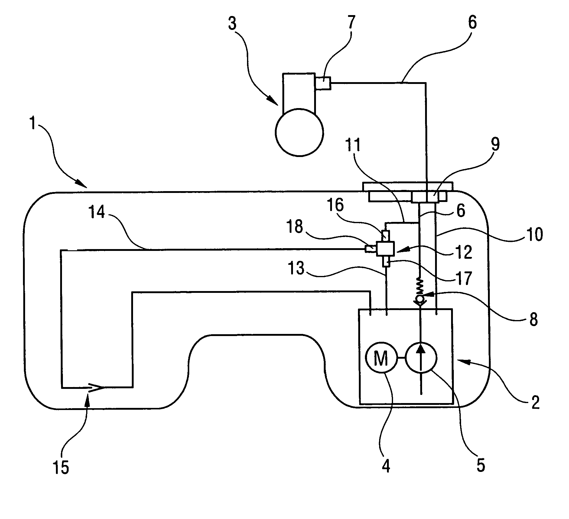
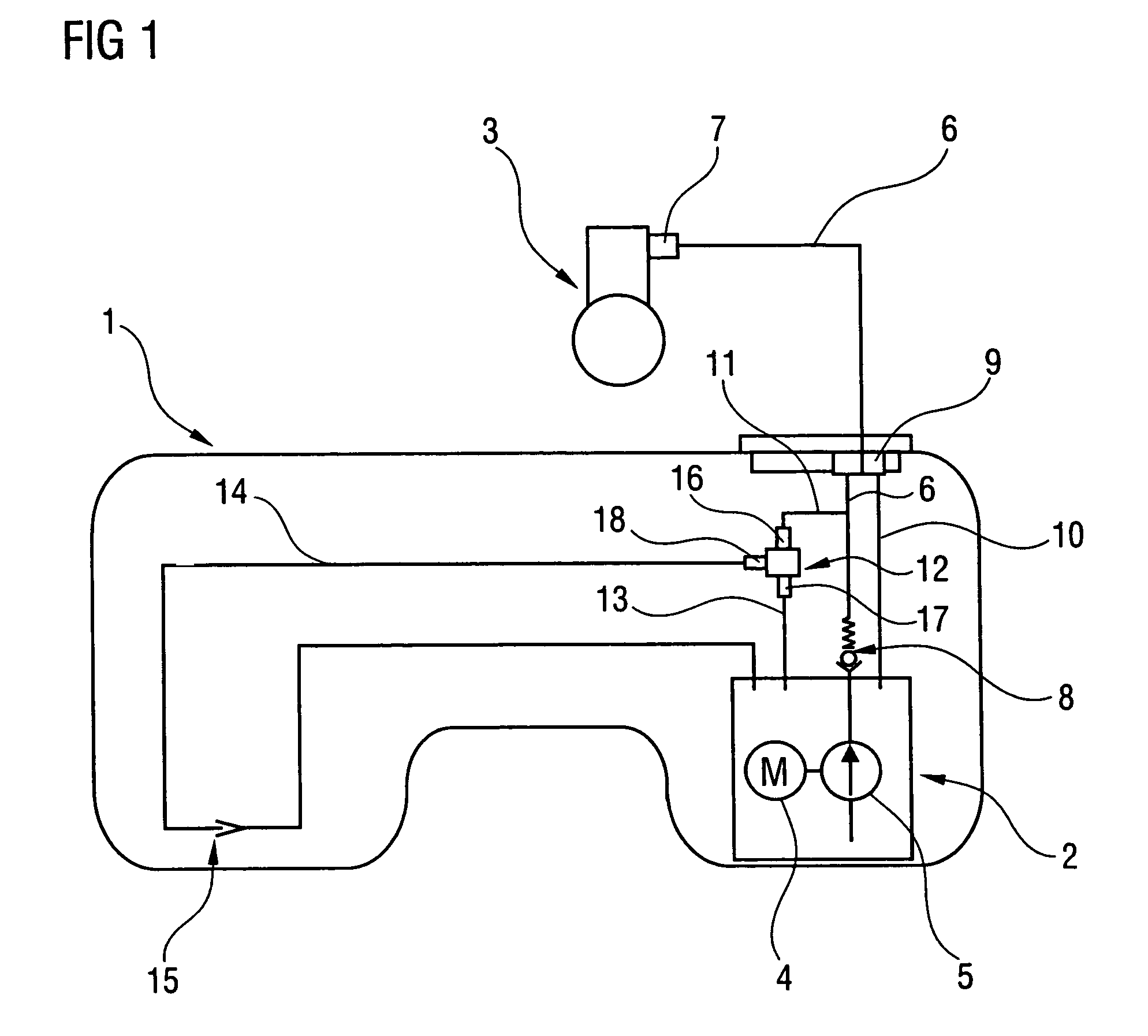
[0021]FIG. 2 diagrammatically shows the apparatus 12 from FIG. 1, in which a shutoff valve 20 and a pressure limiting valve 21 are arranged behind one another in a connection 19 between the inflow junction 16 and the outflow junction 17. The shutoff valve 20 and the pressure limiting valve 21 each have a valve seat 22, 23, the valve seats 22, 23 lying opposite one another and a valve body 24 being movably arranged between the valve seats 22, 23. In the pressureless state shown, the valve body 24 is prestressed by a spring element 25 against the valve seat 23 of the pressure limiting valve 21. The junction 18 of the fuel line 14 from FIG. 1 which leads to the suction jet pump 15 is arranged between the pressure limiting valve 21 and the shutoff valve 20. Furthermore, the apparatus 12 has webs 26 for guiding the valve body 24 which are arranged between the valve seats 22, 23. The valve body 24 has a disk 36 which is made from elastomeric material and two supporting disks 37 which are ...

second embodiment

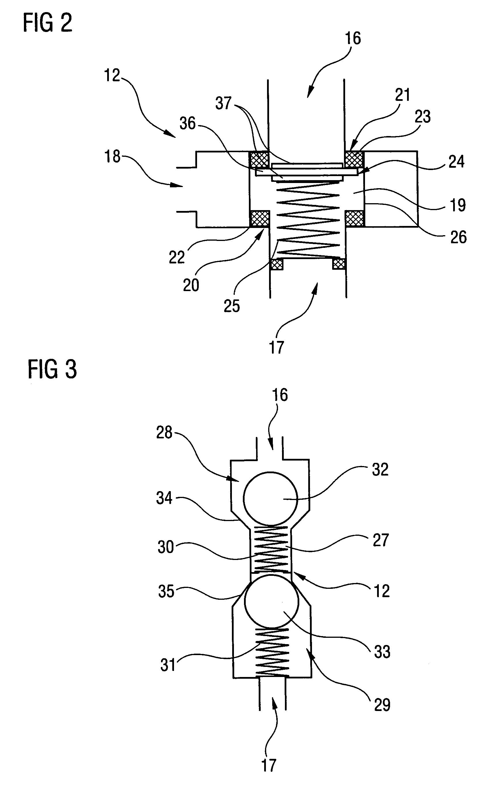
[0023]FIG. 3 diagrammatically shows the apparatus 12 from FIG. 1 in the pressureless state, in which a shutoff valve 28 and a pressure limiting valve 29 are arranged behind one another in a connection 27 between the inflow junction 16 and the outflow junction 17, the shutoff valve 28 being arranged closer to the inflow junction 16 than the pressure limiting valve 29. The shutoff valve 28 and the pressure limiting valve 29 each have a valve body 32, 33, which is prestressed by a spring element 30, 31, and a valve seat 34, 35. In a deviation from the apparatus from FIG. 2, this apparatus 12 has no junction for the fuel line 14 which leads to the suction jet pump 15. However, the flow from the inflow junction 16 to the outflow junction 17 is controlled in the same way as described for the apparatus 12 according to FIG. 2.


PUM


Abstract

In an apparatus (12) for controlling a pressure in a fuel inflow line of a motor vehicle, a shutoff valve (20) and a pressure limiting valve (21) are arranged in a connection (19). The connection (19) is arranged between an inflow junction (16) which leads to the inflow line and an outflow junction (17) which is led into a fuel container. The pressure limiting valve (21) opens above a first pressure and throttles the flow of the fuel through the connection (19). The shutoff valve (20) closes above a second pressure, the second pressure being higher than the first pressure. This ensures that, when a fuel delivery unit is at a standstill, the pressure in the inflow line does not exceed the first pressure and that, during operation of the delivery unit, the pressure in the inflow line can rise above the second pressure and an internal combustion engine of the motor vehicle is supplied sufficiently with fuel.

Description

BACKGROUND OF THE INVENTION[0001]The invention relates to an apparatus for controlling a pressure in a fuel inflow line of a motor vehicle, having an inflow junction which is provided for connecting to the inflow line and having an outflow junction which is provided for returning fuel into a fuel container, and having a valve which is arranged in a connection between the inflow junction and the outflow junction.[0002]In order to limit a pressure provided in an inflow line, pressure limiting valves have been disclosed which open above a predefined pressure and lead excess fuel back into the fuel container. The maximum pressure which is fed to the internal combustion engine is therefore limited.[0003]In modern motor vehicles, however, there is the problem that fuel can emerge from an injection nozzle of the internal combustion engine after the internal combustion engine has been switched off. This fuel cannot flow back into the fuel container on account of a nonreturn valve which is a...

Claims


Application Information

Patent Timeline
Patent Type & Authority Patents(United States)
IPC IPC(8): F02M37/00F02M37/10F02M59/46F02M63/00
CPCF02M37/106F16K15/028F16K17/044F16K17/0406F16K17/0413F16K15/042
Inventor DICKENSCHEID, LOTHARHERZOG, BERND
Owner CONTINENTAL AUTOMOTIVE GMBH
Why Eureka
Try Eureka