Method for mounting a pneumatic tire

a technology of pneumatic tires and mounting methods, which is applied in the field of mounting methods of pneumatic tires, can solve the problems that tires cannot perform any uncontrolled movement, and achieve the effects of low structural complexity, simple setup and optimization, and low cos

Active Publication Date: 2010-04-20
SCHENCK ROTEC GMBH
View PDF18 Cites 35 Cited by
  • Summary
  • Abstract
  • Description
  • Claims
  • Application Information

AI Technical Summary

Benefits of technology

[0008]It is an object of the invention to provide a method for at least one-sided automatic mounting of pneumatic tires on well base rims, which method is kind to the pneumatic tires during mounting, is suitable for a series of different combinations of well base rims and pneumatic tires and is easy to set up. It is a further object of the invention to provide an apparatus suitable for carrying out the method, which apparatus is distinguished by low structural complexity and may be simply set up and optimized.
[0010]The method according to the invention has the advantage that the manipulator may perform predetermined or freely programmable positioning and movement of the tire corresponding precisely to the mounting requirements. The forces and moments which arise during mounting remain smaller than with the hitherto known mounting methods. The tire is therefore protected. Since the manipulator holds the tire during the mounting procedure, the tire cannot perform any uncontrolled movements. It is thus ensured that the set and optimized movement sequence is observed. The method according to the invention has the additional advantage of being largely independent of the construction of the tire and the construction of the rim or the dimensions thereof. To hold and clamp different tire and rim sizes, it is sufficient to adjust accordingly the working stroke of the devices for holding and clamping and the positioning and movement of the tire. Conventionally, these movement sequences are controlled by means of a programmable servo controller, for example a CNC controller, such that the system may in each case be set up simply for the intended application by inputting application-specific data and programs.
[0011]A further advantage of the method according to the invention is that the manipulator may be used to fetch the tire to be mounted from a conveyor means delivering the tire, move it to a soaping station and then mount it. During the entire sequence, the tire is held and guided by the manipulator. This allows high conveying speeds and correspondingly short cycle times and prevents incorrect positioning of the tire on transfer from one conveyor means to the next.
[0013]The method according to the invention may be used for mounting just one tire bead or, in suitable cases, also for mounting both tire beads. If it is intended that automatic mounting of a very large number of different tire types should be possible, according to the invention the first tire bead may be mounted by means of the manipulator in accordance with the method indicated in claim 1 and the second tire bead may be mounted using a downstream, conventional mounting means with mounting tools passed along the rim flange. Such a combination of the two procedures makes possible short cycle times, if the two mounting methods may be used simultaneously, and may even be used when only the conventional procedure is possible due to the tire or rim construction.
[0018]The method according to the invention is additionally characterized in that, prior to mounting of the pneumatic tire, the latter is conveyed by the manipulator to a soaping station for soaping the tire beads with lubricant and in the soaping station is moved with the tire beads along an application means for the lubricant. This method step makes it possible for the soaping station to be of a very simple, inexpensive design, without the need for moving application means and special conveyor means.

Problems solved by technology

Since the manipulator holds the tire during the mounting procedure, the tire cannot perform any uncontrolled movements.

Method used


Image

  • Method for mounting a pneumatic tire
  • Method for mounting a pneumatic tire
  • Method for mounting a pneumatic tire

Examples


Embodiment Construction

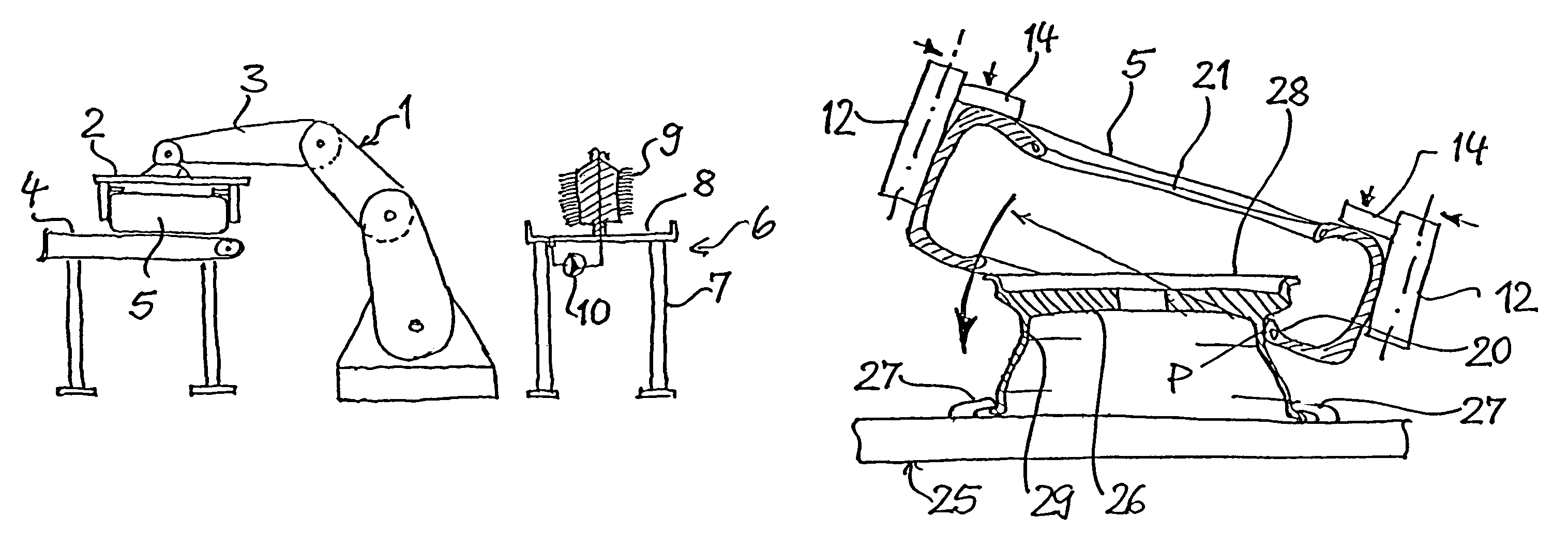
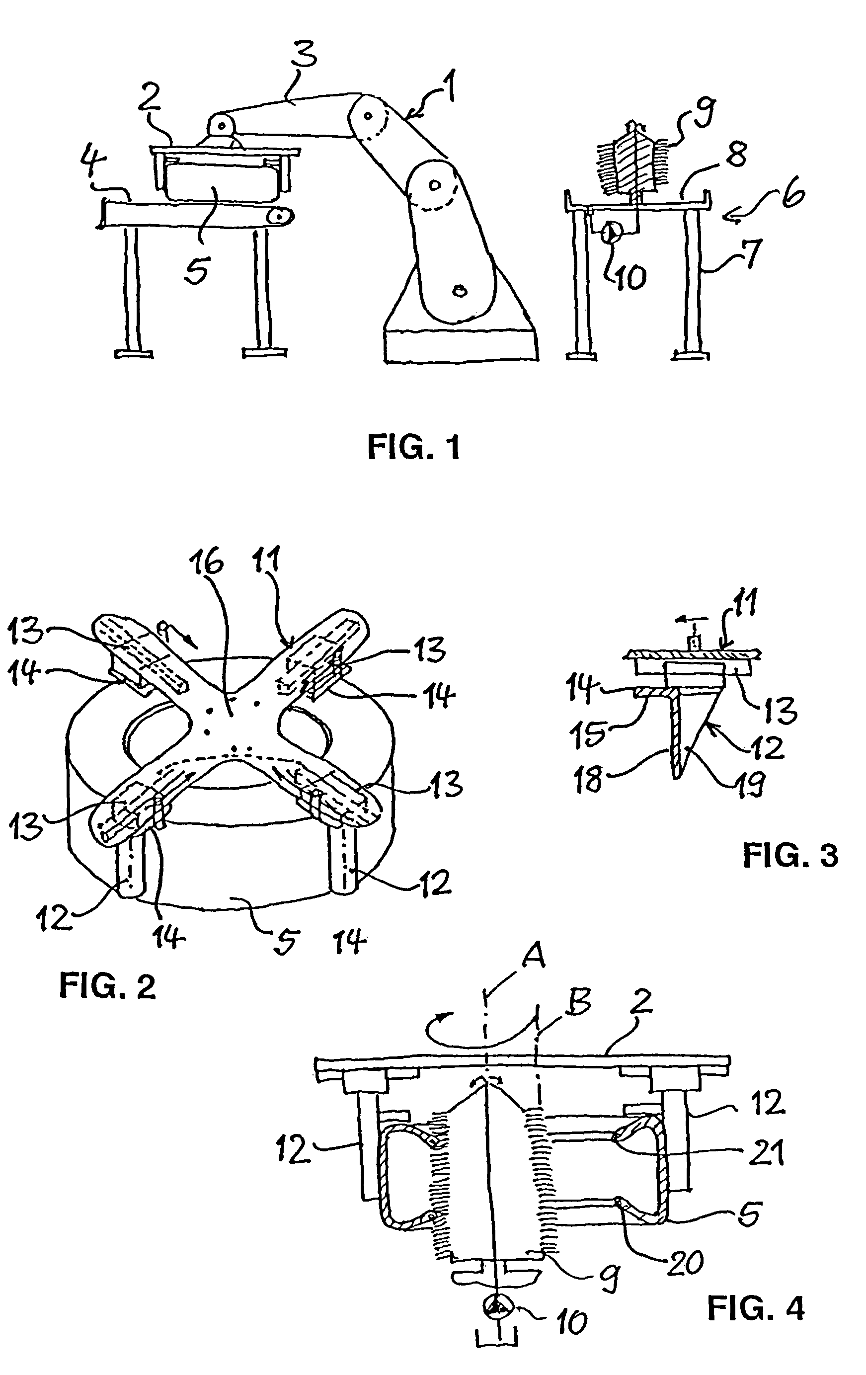
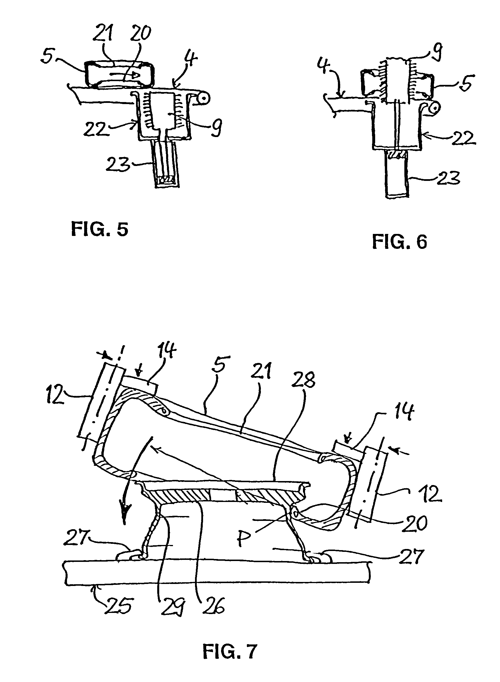
[0031]FIG. 1 shows a manipulator 1 with a gripper 2, which is intended for tire mounting according to the above-described method. The manipulator 1 is an industrial robot with an articulated arm 3 comprising a plurality of movement axes, by means of which the gripper may be moved in three spatial directions. In addition, the gripper 2 is connected to the articulated arm 3 so as to be rotatable about two axes. The manipulator comprises a plurality of independent drives, which may be controlled by a programmable control means and allow precisely positioned movement of the gripper 2.

[0032]Within the working range of the manipulator 1, there is located the end of a conveyor means 4 for intermittent delivery of the pneumatic tires 5 to be mounted to the manipulator 1. Also located within the working range of the manipulator 1 is a soaping station 6, which serves to soap the tire beads with a lubricant prior to mounting. The soaping station 6 comprises a table 7 with a shallow trough 8, i...


PUM


Abstract

Method for mounting a pneumatic tire on a well base rim of a motor vehicle wheel, in which the pneumatic tire is grasped by means of a manipulator, brought up to a rim held in a clamping device and slipped with at least the one tire bead facing the rim over a rim flange by controlled movement of the manipulator.

Description

CROSS-REFERENCE TO RELATED APPLICATION[0001]This application claims the benefit of German Patent Application No. 10 2005 030 692.6 filed Jun. 29, 2005, and of European Patent Application No. 06 113 649.5 filed on May 8, 2006, both applications incorporated herein by reference.FIELD OF THE INVENTION[0002]The invention relates to a method for mounting a pneumatic tire on a well base rim of a motor vehicle wheel and to an apparatus for carrying out the method.BACKGROUND OF THE INVENTION[0003]In a hitherto conventional method for mechanical mounting of vehicle wheels, the rim is held firmly in a horizontal position by means of a clamping device, with the rim dish facing up- or downwards. The pneumatic tire is placed on the rim at an angle and pushed thereonto until the lower tire bead is forced with a lower portion into the rim well base, while it projects with its upper portion over the upper rim flange. Then fitting tools are lowered onto the tire and the rim from above and press the ...

Claims


Application Information

Patent Timeline
Patent Type & Authority Patents(United States)
IPC IPC(8): B60C25/00B60C25/122
CPCB60C25/0515B60C25/0533B60C25/132B60C25/0596B60C25/0554
Inventor ROGALLA, MARTINLEMSER, MATTHIASPEINELT, ANDREASLIPPONER, GEORG
Owner SCHENCK ROTEC GMBH
Why Eureka
Try Eureka