
Device for detecting the state of a machine element

Inactive Publication Date: 2015-07-09
CLAAS SELBSTFAHRENDE ERNTEMASCHINEN GMBH
View PDF7 Cites 0 Cited by
  • Summary
  • Abstract
  • Description
  • Claims
  • Application Information

AI Technical Summary

Benefits of technology

The present invention is a device that can detect the movement of a rotating machine part and measure its torque and speed. It is designed to be compact and easy to use. Its unique features make it better than other devices in the market.

Problems solved by technology

The disadvantage of this method is the amount of outlay that is required, in terms of installation space and costs, to detect the angle of rotation at two points that are spaced apart from one another.
In addition, performing an exact measurement at relatively high rotational speeds is either not possible or requires considerably complex measurement technology.
A disadvantage of this type of detection, however, is the difficulty of transmitting the measurement signal from the rotating measurement point correctly and without interference.
This requires installation space and, due to the measurement technology that is required, generates costs that are not inconsequential.

Method used


Image

  • Device for detecting the state of a machine element
  • Device for detecting the state of a machine element

Examples


Embodiment Construction

[0030]The following is a detailed description of example embodiments of the invention depicted in the accompanying drawings. The example embodiments are presented in such detail as to clearly communicate the Invention and are designed to make such embodiments obvious to a person of ordinary skill in the art. However, the amount of detail offered is not intended to limit the anticipated variations of embodiments; on the contrary, the intention is to cover all modifications, equivalents, and alternatives falling within the spirit and scope of the present invention, as defined by the appended claims.

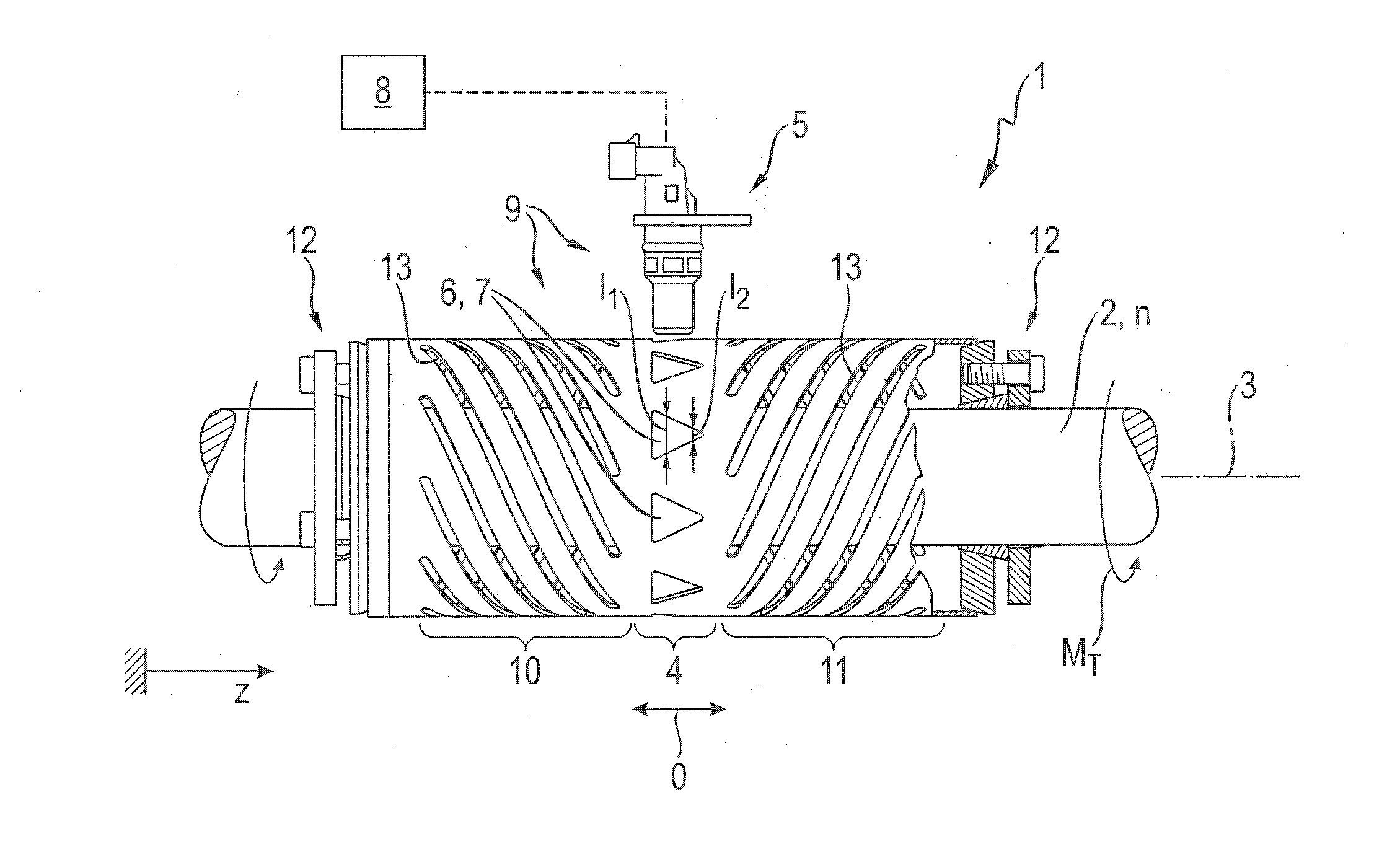
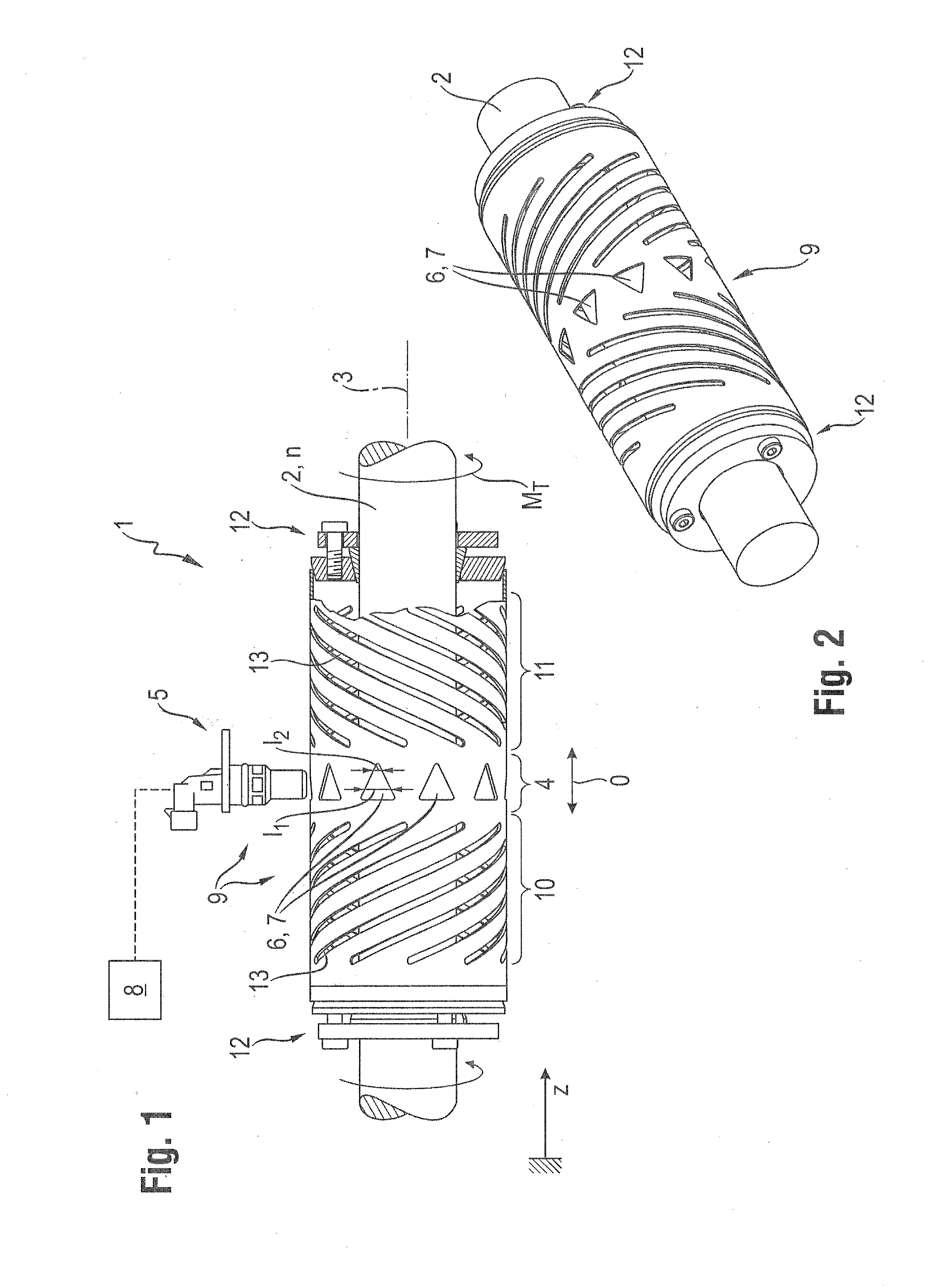
[0031]FIG. 1 shows a device 1 for detecting the mechanical state of a continuous shaft 2 according to an exemplary embodiment of the invention, in a side view. Shaft 2 rotates about an axis 3 in order to transmit mechanical drive power between machine components, which are not illustrated here. This can be, for example, a shaft within a drive train (e.g., the ground drive) of an agricultura...


PUM


Abstract

A device for detecting a mechanical state of a machine element rotates about an axis, such as a shaft is formed with an actuator disposed on the machine element so as to be axially movable, an arrangement for converting a torsion of the machine element into an axial displacement of the actuator and a sensor disposed so as to be stationary relative to the machine element for detecting the axial displacement of the actuator. A mark is assigned to the actuator for detection by the sensor in order to detect the axial displacement of the actuator. A speed (n) of the machine element can be determined from the number of marks that are detected per unit of time.

Description

CROSS-REFERENCE TO A RELATED APPLICATION[0001]The invention described and claimed hereinbelow is also described in German Patent Application DE 10 2014 100 124.9, filed on Jan. 8, 2014. The German Patent Application, the subject matter of which is incorporated herein by reference, provides the basis for a claim of priority of invention under 35 U.S.C. 119(a)-(d).BACKGROUND OF THE INVENTION[0002]The present invention relates to a device for detecting the mechanical state of a machine element that can rotate about an axis.[0003]Agricultural working machines, such as tractors, harvesting machines, attachments and the like, utilize rotatable machine elements, in particular, (drive) shafts in highly diverse application forms in order to drive highly diverse assemblies and, very generally, in order to transfer mechanical drive power between these assemblies. In this connection there is often a need, depending on the particular application, to detect the torque transferred by the machine e...

Claims


Application Information

Patent Timeline
IPC IPC(8): G01L3/08G01P3/36G01L5/00
CPCG01L3/08G01P3/36G01L5/0061G01L3/06
Inventor ELLERMANN, KLAUSDAEHNE, GOETZ
Owner CLAAS SELBSTFAHRENDE ERNTEMASCHINEN GMBH
Learn More