Spatula for stirring bowls

a technology for stirring bowls and spatulas, which is applied in the field of spatulas, can solve the problems of mixing in the region of the stirring unit, difficult to use spatulas of the described type, and large amounts of mix remaining in the bowl

Active Publication Date: 2022-01-25
WUNDERLE JOHANNES
View PDF10 Cites 2 Cited by
  • Summary
  • Abstract
  • Description
  • Claims
  • Application Information

AI Technical Summary

Benefits of technology

[0018]The object of the invention is therefore to provide an apparatus and a method which avoid the drawbacks of the prior art. Accordingly, the apparatus according to the invention shall be suitable for the effective, i.e. fast and as complete as possible removal of solid as well as of liquid mix from stirring bowls and the same, and in particular in cases when they have a stirring unit which is guided through the bottom. Injure of the user by using the apparatus shall be excluded, as well as damage of the stirring unit, or jamming of the apparatus therewith. Also, the danger of unintended operation of the stirring unit shall be reduced. Further, use of the apparatus shall largely be independent from a user's experience.SUMMARY OF THE INVENTION

Problems solved by technology

While the former can have a bowl with virtually completely smooth inner walls, this is not the case with the latter due to its design, since a bushing for the mixing unit is needed which typically is located in the centre of the bottom of the bowl.
Usage of spoons, scoops or the same also results in comparably large amounts of mix remaining in the bowl.
The usage of spatulas of the described type is problematic in particular with regard to bowls that have a stirring unit which is located at the bottom, inasmuch as the unit impedes the scraping guiding of the spatula along the bottom area.
As a result, mix remains in the region of the stirring unit, which is undesired.
Further, sharp-edged parts of the stirring unit can damage the working element of the spatula, which is preferably, as mentioned, made from soft material in order to adapt to the different contours of the inner region of the bowl (side, transition region, bottom).
Insofar, the working result (speed, thoroughness) of using a spatula depends on the actual user, which is a disadvantage.
However, usage of a shield is impractical with regard to common stirring bowls having a very large opening, since the shield would have to be very large as well.
Further, the proposed spatula does not solve the problem of removing mix adhering to region of the stirring unit.
Also, the spatula fails at removing liquid mix.
In the case of particularly liquid mix, the spatula is hardly usable, since the mix which is already taken up by the spatula's edge and is pushed onto the spatula area quickly drops off the spatula again; a satisfying work result can only be achieved by a very fast or a very frequent repetition of the work motion.
In fact, such a mix can be removed more easily by means of a scoop; however, because of its bulky shape, even more mix remains in the poorly accessible region below the stirring unit and the transition region between inner wall and bottom area, in particular, when the transition region has a very small or very large radius.
Further, also in case of a scoop, damages can occur due to, or of, the stirring unit.
Particularly critical is a situation in which an unintended operation of the rotating components of the stirring unit occurs.
Damage to the spatula or scoop as well as to the stirring unit can hardly be avoided.
Also, the user can injure himself with the suddenly rotating handle.
But even when the stirring unit stands still, the manual removing of mix rests, often exercised with the fingers, from the poorly accessible region of the stirring unit can result in injuries from sharp-edged parts thereof.
However, by means of such a spatula it is impossible to get at the bottom of the vessel.
Furthermore, this spatula also fails during the removal of a liquid mix.

Method used


Image

  • Spatula for stirring bowls
  • Spatula for stirring bowls
  • Spatula for stirring bowls

Examples


Embodiment Construction

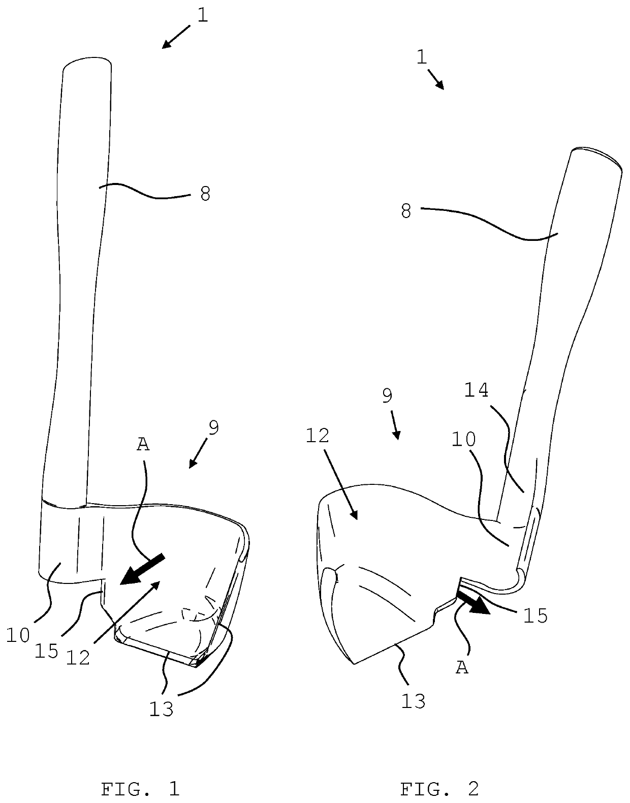
[0067]In FIG. 1, a preferred embodiment of a removal aid according to the invention in a front view is shown; FIG. 2 shows the embodiment of FIG. 1 in a rear view.

[0068]The removal aid 1 includes a handle 8 and a work element 9. Work element 9 includes a centering aid 10 which is designed to cooperate with a stirring unit's end 11 of stirring unit 6, the end pointing towards the opening 3 of a stirring bowl 2 (not shown, respectively). Work element 9 further has a convex reception region 12 with a spatula-like working edge 13 that points towards working direction A. Working edge 13 stretches along the front edge of the underside and along the outward oriented edge of the outside of work element 9.

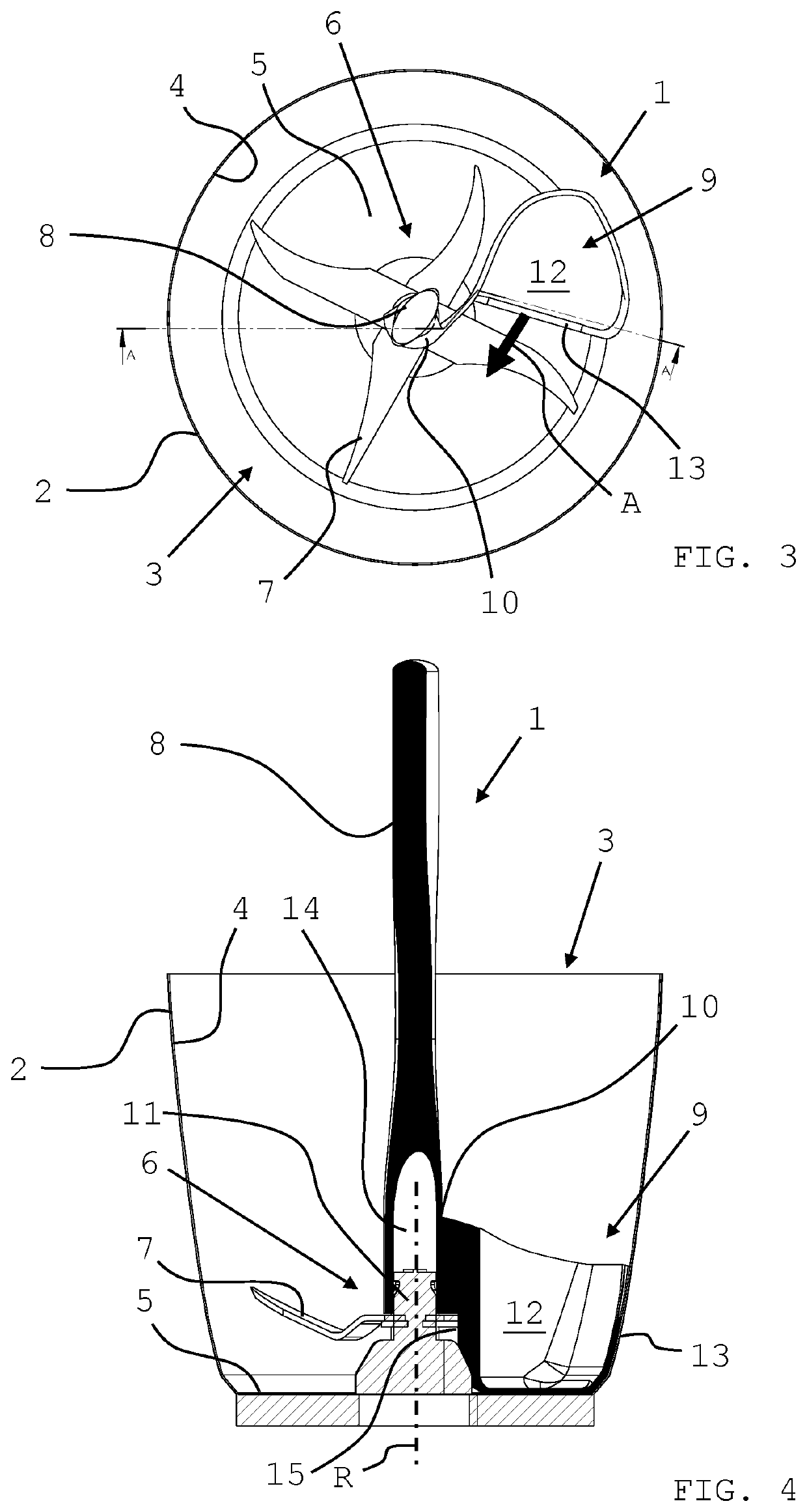
[0069]In FIG. 3, a top view onto a removal aid in working position is shown which is positioned in a stirring bowl, and in FIG. 4, the situation from FIG. 3 is shown in a cross-sectional view.

[0070]Stirring bowl 2 comprises an opening 3, an inner wall 4, a bottom 5, as well as a rotatable s...


PUM


Abstract

The removal aid serves for removal of liquid and solid mix from a stirring bowl, the removal aid having a handle and a work element and is intended for a rotation. The working element has a centering aid which is designed to cooperate with a stirring unit's end of the stirring unit, the end pointing towards the opening, and a convex reception region with a spatula-like working edge that points towards the working direction, so that the removal aid can be centred onto said stirring unit's end and can be rotated in the working direction inside the stirring bowl.

Description

CROSS REFERENCE TO RELATED APPLICATIONS[0001]This is a US national phase application under 35 USC § 371 of international application no. PCT / IB2019 / 057153, filed 26 Aug. 2019, which claims priority to German application no. 102018120928.2, filed 28 Aug. 2018. The applications referred to in this paragraph are herein incorporated by reference in their entireties.TECHNICAL FIELD[0002]The invention relates to a spatula. In particular, the invention relates to a spatula for household area stirring bowls that have a stirring unit which can be guided through the bottom.BACKGROUND OF THE INVENTION[0003]For mixing, crushing or emulsifying foodstuffs in order to produce a mix such as e.g. a dough, a sauce or the like, besides the manual mixing with e.g. a cooking spoon or whisk, electrically driven stirring machines, often simply called “food processors”, are commonly used.[0004]Amongst others, such a food processor comprises a container (stirring bowl, mixing cup), and a stirring unit which...

Claims


Application Information

Patent Timeline
Patent Type & Authority Patents(United States)
IPC IPC(8): A47J43/07A47J43/28B01F7/00B01F15/00
CPCA47J43/288A47J43/0716A47J43/0722B01F7/00208A47J43/0727B01F15/00058A47J43/28B01F27/091B01F35/123
Inventor WUNDERLE, JOHANNES
Owner WUNDERLE JOHANNES
Why Eureka
Try Eureka