Structures for use in erecting multistory buildings and methods for making such structures

a multi-story building and structure technology, applied in pretreatment control, construction, building construction, etc., can solve the problems of time-consuming and expensive construction of elevator shafts, requiring repeated heavy labor, and requiring time-consuming and expensive construction

Active Publication Date: 2022-01-25
RANDALL ENGINEERED WALL SYST INC
View PDF11 Cites 1 Cited by
  • Summary
  • Abstract
  • Description
  • Claims
  • Application Information

AI Technical Summary

Benefits of technology

[0006]The disclosed construction methods provide an advantage by allowing an elevator shaft to be rapidly assembled at a jobsite prior to any floors being constructed.
[0007]Another advantage is that the disclosed construction allows for an elevator shaft to be made in a series of segments, all of which can be formed and assembled at a location that is remote from the jobsite.
[0008]A further advantage of the present construction is that it allows for floor slabs to be formed about a fully assembled elevator shaft.
[0009]Still yet another advantage of the present method is that it allows for an improved connection between the elevator shaft and the surrounding floor slab.
[0010]Another advantage is that the form work and reinforcing cages typically associated with elevator shafts no longer have to assembled on the jobsite.

Problems solved by technology

However, elevator shafts are time consuming and expensive to build, requiring heavy labor to be repeated for each floor of the building.
It is for this reason that elevator shafts have a large impact on project schedules and are often the limiting factor in meeting project deadlines.
Although the various systems of the background art each achieve their own unique objectives, all suffer from drawbacks.
Namely, the background art fails to disclose constructions and methods that allow for the rapid installation of an elevator shaft at a jobsite and that further allows the shafts to be constructed prior to the surrounding floors.

Method used


Image

  • Structures for use in erecting multistory buildings and methods for making such structures
  • Structures for use in erecting multistory buildings and methods for making such structures
  • Structures for use in erecting multistory buildings and methods for making such structures

Examples


Embodiment Construction

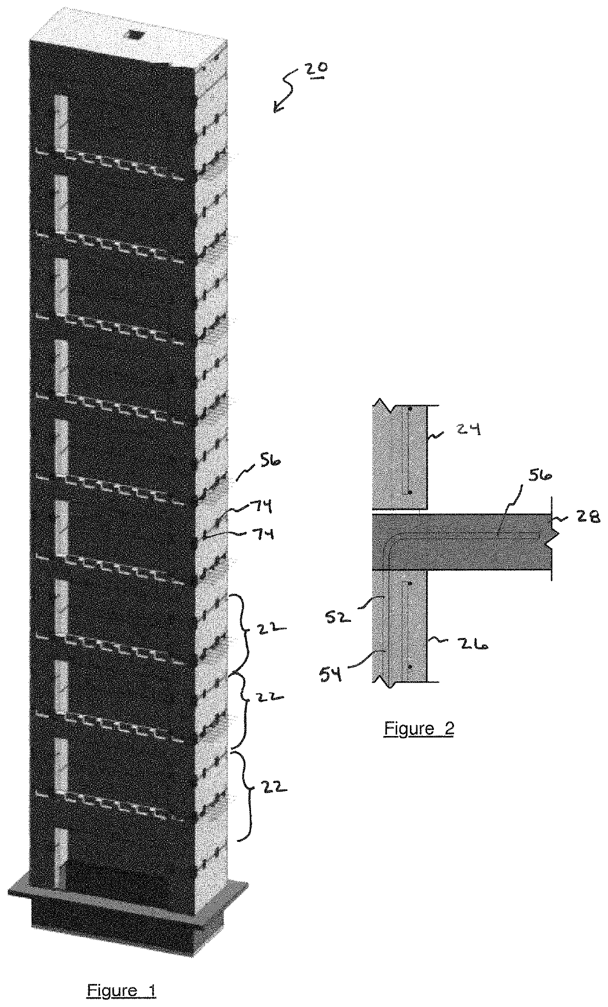
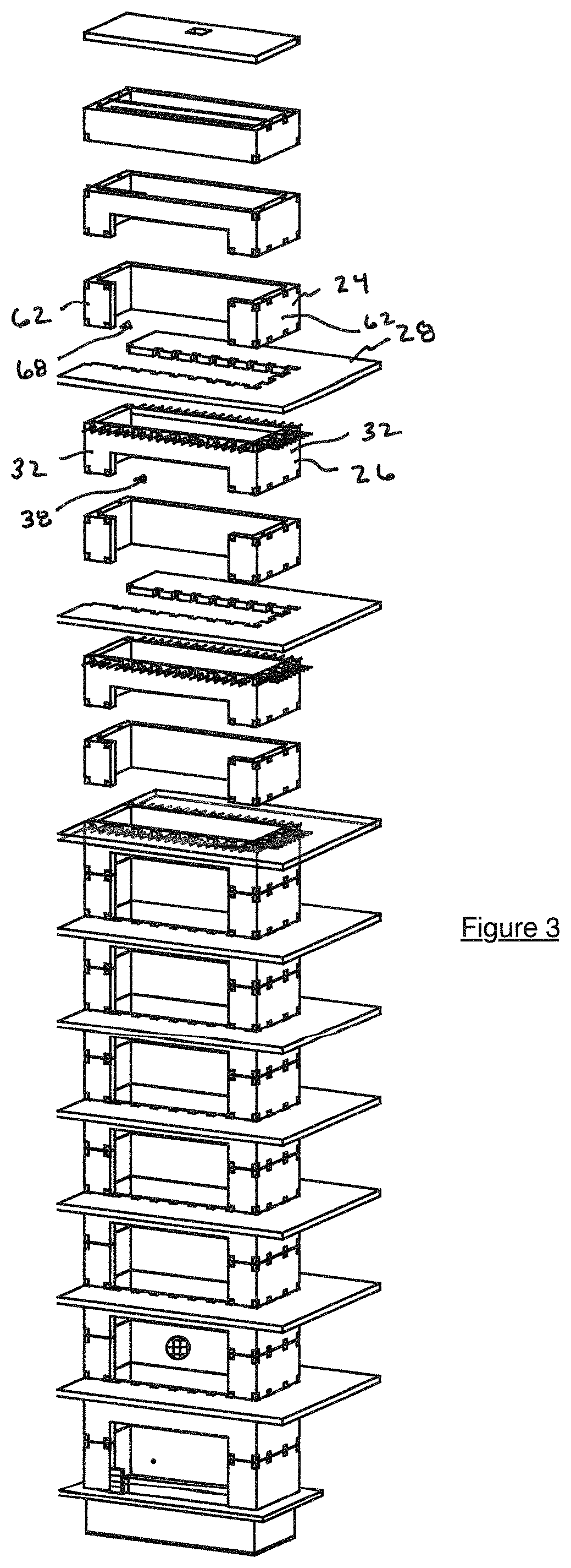
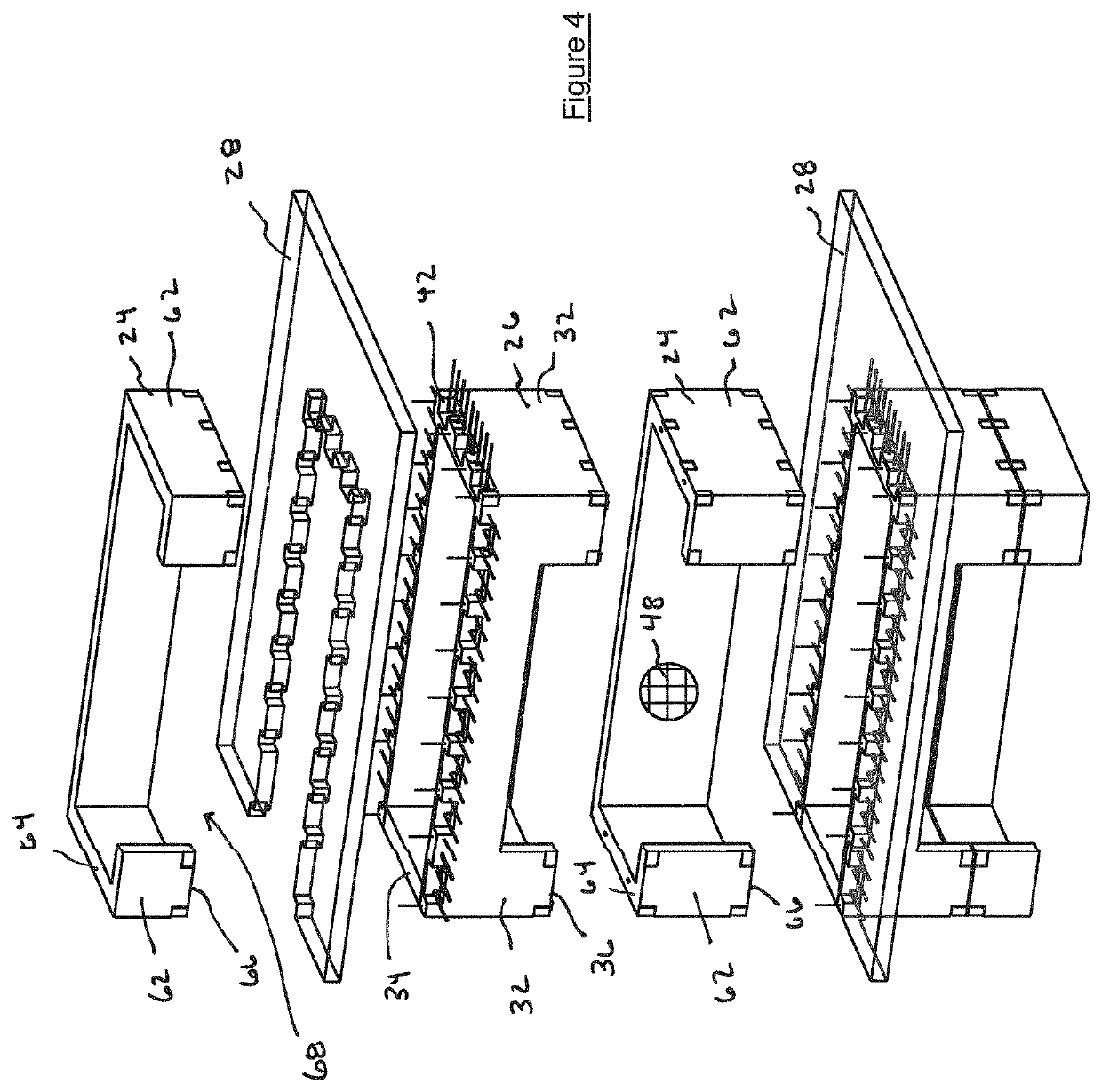
[0023]The present disclosure relates to a construction method for erecting an elevator shaft for a multistory building. In accordance with the method, upper and lower shaft components are formed at an offsite facility. These shaft components are then joined together to form a segment of the larger elevator shaft. Once constructed, the segment is transported to a jobsite and erected. Once an individual segment is installed, a floor slab can be formed about the segment. Using pre-cast elevator segments simplifies and expedites the construction process. In one embodiment, each segment includes a serrated edge that facilitates a connection between the floor slab and the shaft segment. Rebar and reinforcing dowels can also be used to improve the connection. Associated shaft constructions are also disclosed. The various components of the present disclosure, and the manner in which they interrelate, are described in greater detail hereinafter.

[0024]With reference now to FIG. 1, the modular...


PUM


Abstract

Disclosed are various construction techniques for erecting a multistory building with an elevator shaft. In accordance with the method, upper and lower shaft components are formed at an offsite facility. These shaft components are then joined together to form a segment of the larger elevator shaft. Once constructed, the segment is transported to a jobsite and erected. Once an individual segment is installed, a floor slab can be formed about the segment. Using pre-cast elevator segments simplifies and expedites the construction process. In one embodiment, each segment includes a serrated edge that facilitates a connection between the floor slab and the shaft segment. Rebar and reinforcing dowels can also be used to improve the connection. Associated shaft constructions are also disclosed.

Description

BACKGROUND OF THE INVENTIONField of the Invention[0001]The present disclosure relates to structures for use in erecting multistory buildings. More particularly, the present disclosure relates to a modular elevator shafts and associated assembly techniques.Description of the Background Art[0002]Elevator shafts are a critical component of any multistory building project. However, elevator shafts are time consuming and expensive to build, requiring heavy labor to be repeated for each floor of the building. At each floor, a rebar cage must be assembled and secured in place. A crane is, thereafter, used to install formwork around the rebar cage. Concrete must then be poured into the formwork, often with the use of a boom pump. The poured concrete requires several days to cure. Once dried, a crane is again used to remove the formwork. Only after all these steps have been carried out, can the surrounding floor slab be formed. Once the floor slab has sufficiently cured, the process is then ...

Claims


Application Information

Patent Timeline
Patent Type & Authority Patents(United States)
IPC IPC(8): E04B1/348E04B1/04B28B7/22
CPCE04B1/34823B28B7/22E04B1/043B28C7/003E04B1/04
Inventor SHUMATE, MARK
Owner RANDALL ENGINEERED WALL SYST INC
Why Eureka
Try Eureka