Active compression apparatus, methods of assembly and methods of use

a compression screw and active technology, applied in the field of general surgery and orthopedic implants, can solve the problems of inability of the static device to maintain the compressive load, the current active compression screw concept is limited in its ability to change the length, and the concept of complex surgical procedures, etc., to facilitate the change of a dimension of the apparatus, promote the healing of fractures or fusions, and facilitate the effect of changing the dimension of the apparatus

Active Publication Date: 2022-02-01
ACTIVORTHO INC
View PDF201 Cites 0 Cited by
  • Summary
  • Abstract
  • Description
  • Claims
  • Application Information

AI Technical Summary

Benefits of technology

[0009]It is known that the time period of application of the desired applied force is until the bone is fused. In certain embodiments of the present invention, an apparatus and method are provided in which the apparatus provides active compression to bone segments for a time exceeding current compression screws and up to the time for the bones to heal or fuse. The amount of force needed to facilitate bone healing over time may change. However, the present invention allows for structural variables to be adjusted such that the inventive apparatus delivers a compressive axial force in different amounts over time and stretched lengths. Additionally, such structural variables can be adjusted to deliver a consistent amount of force over a given distance or time. The devices of the present invention have the ability to be scaled down to an effective diameter for use in the small bones of the hand and feet having diameters potentially less than 2 mm.
[0010]An activation of an axial tension force according to the present invention can be before, during, or after deployment of the device into the desired anatomy, thus allowing for different surgical procedures to be developed and optimized for clinical benefit. To facilitate a common surgical procedural approach of first deploying a guide pin or K-wire and then performing the delivery of the device over that member, the apparatuses of the present invention can be cannulated. Alternatively, the apparatuses of the present invention can be non-cannulated or solid. The current invention can incorporate all other known existing features that facilitate tissue interaction and compression generation.
[0013]The present invention is further directed to joining members, such as active bone screws and methods of use thereof for securing portions of tissue and / or bones while providing a specific amount of desired flexion or elasticity that promotes stronger healing of a fracture or fusion, e.g. resulting in increased torsional strength of a healed fracture or fusion. The present invention is further directed to joining members, such as active rods and / or plates and methods of use thereof for securing portions of tissue and / or bones while providing a specific amount of desired flexion or elasticity that promotes stronger healing of a fracture or fusion, e.g. resulting in increased torsional strength of a healed fracture or fusion.
[0016]Certain embodiments of the present invention provide an apparatus for generating active compression comprising: a distal bone engagement portion; a proximal bone engagement portion having an external diameter greater than an external diameter of the distal bone engagement portion; and a central portion interposed between the proximal bone engagement portion and the distal bone engagement portion having a perforation formed there through that facilitates a change in a dimension of the apparatus. Wherein the apparatus has a unitary contiguous structure. Wherein the apparatus is cannulated. Wherein the proximal bone engagement portion comprises threads having a pitch that is distinct from a pitch of threads of the distal bone engagement portion. Wherein the distal bone engagement portion comprises threads. Wherein the perforation comprises a non-uniform shape. Wherein the perforation comprises a helical form. Wherein the change in the dimension of the apparatus comprises a change in length. Wherein the change in the dimension of the apparatus comprises a shortening of a length of the apparatus. Wherein the change in the dimension of the apparatus comprises a change in dimension of the apparatus over a period of greater than 12 hours.
[0022]Certain embodiments of the present invention provide a method of actively compressing bone segments comprising: inserting a cannulated screw into a first bone segment and a second bone segment; applying a longitudinal tensile stress to a cannulated body through deformation of a perforation formed through a sidewall of the cannulated body; limiting the deformation of the perforation by engaging corresponding deformation limiting features formed in opposing sidewalls of the perforation; releasing the tensile stress over a period of time; and compressing the first bone segment and the second bone segment through said releasing the tensile stress. Wherein inserting the cannulated screw into the first bone segment and the second bone segment and applying the longitudinal tensile stress to the cannulated body through deformation of a perforation formed through the sidewall of the cannulated body are simultaneous; inserting the cannulated screw into the first bone segment and the second bone segment and applying the longitudinal tensile stress to the cannulated body through deformation of a perforation formed through the sidewall of the cannulated body are simultaneous; applying the longitudinal tensile stress to the cannulated body through deformation of a perforation formed through the sidewall of the cannulated body comprises rotating a plurality of threads having different pitches formed on an exterior of the sidewall of the cannulated body; and / or limiting the deformation of the perforation by engaging corresponding deformation limiting features formed in opposing sidewalls of the perforation comprises limiting an increase in a length or an increase in circumference of the cannulated body.

Problems solved by technology

Although a compressive force from a standard screw placement is dynamic during its application, once the screw is tightened down, it functions as a static device unable to maintain the compressive load as the bone remodels.
However, these concepts have complicated surgical procedures.
The current active compression screw concepts are limited in their ability to change length per the ratio of screw length, and they are limited in the amount of axial force per the ratio of screw length.
The current active compression screw concepts do not have the ability to adjust compression or have adjustable compression over time.
The current active compression screws concepts do not have simple construction, making manufacturing complicated and expensive, and finally the current platforms cannot scale down to a therapeutic diameter for small bones.

Method used


Image

  • Active compression apparatus, methods of assembly and methods of use
  • Active compression apparatus, methods of assembly and methods of use
  • Active compression apparatus, methods of assembly and methods of use

Examples


Embodiment Construction

[0240]Specific embodiments of the invention will now be described with reference to the accompanying drawings. This invention may, however, be embodied in many different forms and should not be construed as limited to the embodiments set forth herein; rather, these embodiments are provided so that this disclosure will be thorough and complete, and will fully convey the scope of the invention to those skilled in the art. The terminology used in the detailed description of the embodiments illustrated in the accompanying drawings is not intended to be limiting of the invention. In the drawings, like numbers refer to like elements.

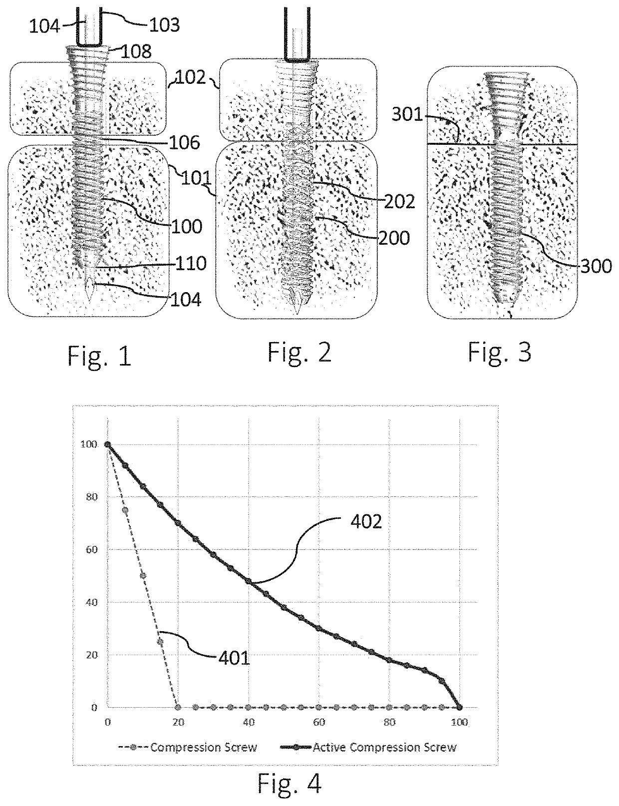
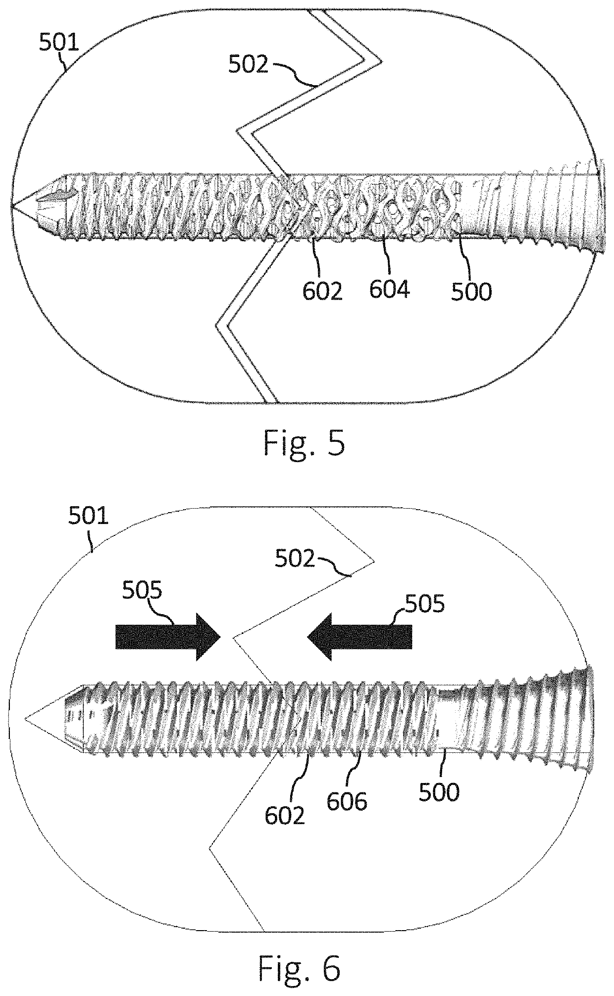
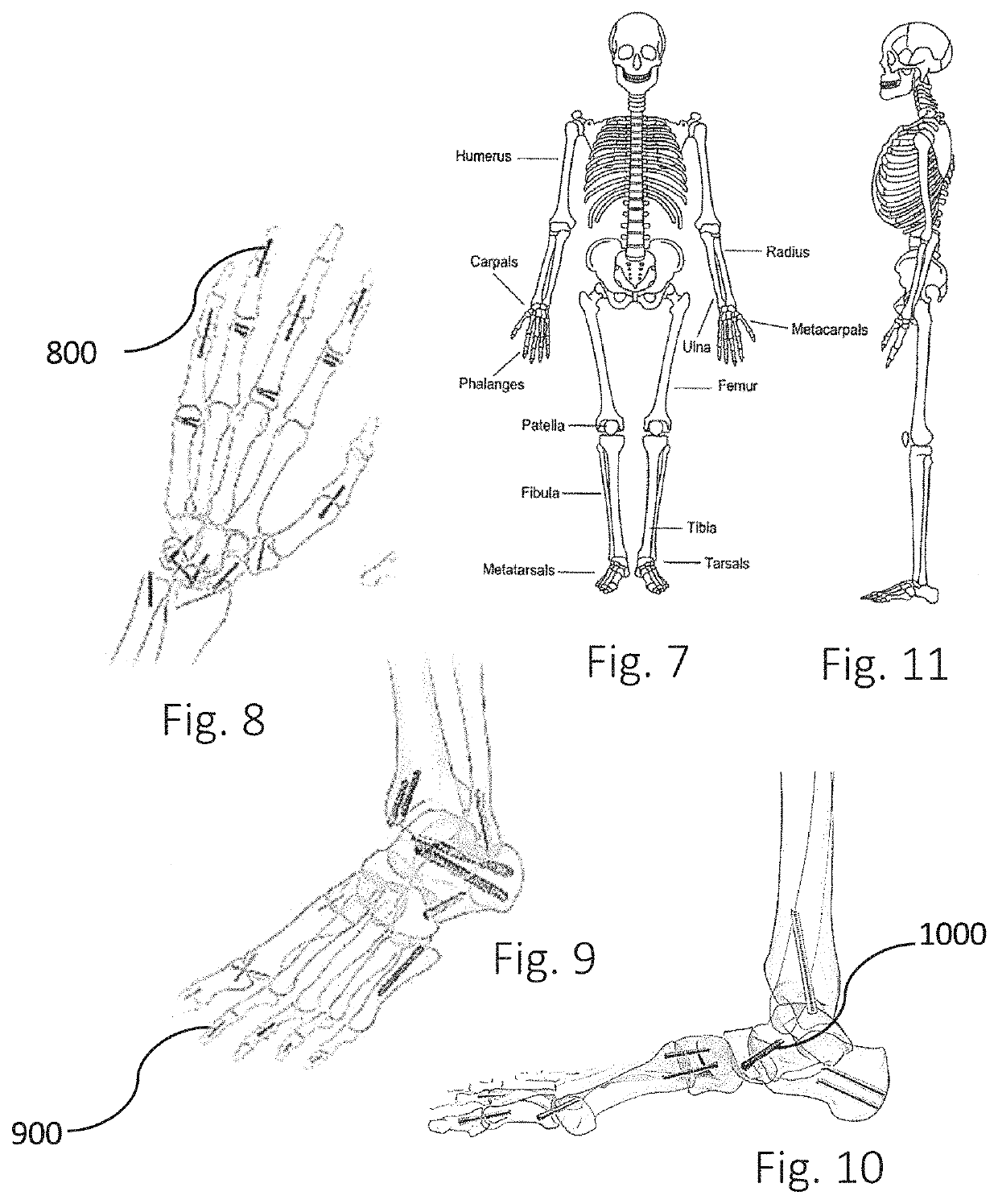
[0241]The present specification describes embodiments of apparatus and methods providing an actively compressing system that compress and secures bone segments. In one embodiment of the present invention, a structure of an orthopedic bone system is pre-loaded prior to insertion or effectively loaded during insertion into a desired orthopedic site to post-opera...


PUM


Abstract

Compression devices for joining tissue and methods for using and fabricating the same.

Description

RELATED APPLICATIONS[0001]This application is a continuation-in-part application of International Application No. PCT / US2017 / 019530 filed Feb. 24, 2017 entitled Active Compression Apparatus, Methods of Assembly and Methods of Use, which claims priority to and benefit of U.S. Provisional Application Ser. No. 62 / 300,336 filed Feb. 26, 2016 entitled Active Compression Apparatus, Methods of Assembly and Methods of Use, which are hereby incorporated herein by reference in their entireties.FIELD OF THE INVENTION[0002]The present invention relates generally to general surgery and orthopedic implants, and more specifically, but not exclusively, relates to devices implanted to aide bone fusion and repair. The invention relates to compression devices for joining two bone fragments, and associated devices for implanting such devices, to methods for compressing and / or fixing bone fragments for extended periods of time, and to the manufacturing of such devices.BACKGROUND OF THE INVENTION[0003]Bo...

Claims


Application Information

Patent Timeline
Patent Type & Authority Patents(United States)
IPC IPC(8): A61B17/86A61B17/72A61B17/84A61B17/88
CPCA61B17/863A61B17/7225A61B17/844A61B17/866A61B17/869A61B17/8685A61B17/8894A61B17/8695A61B17/888A61B17/8888A61B17/8605A61B17/8625A61B17/8615A61B17/86A61B17/686A61B17/864A61B2017/681
Inventor PETERSON, ALEXSAVAGE, DANIEL S.HINDRICHS, PAUL J.PALMER, ANDREW K.BRENZEL, MICHAEL P.OGILVIE, WILLIAM F.
Owner ACTIVORTHO INC
Why Eureka
Try Eureka