Telemetric orthopaedic implant

a telemetry and orthopaedic technology, applied in the field of orthopaedic implants, can solve the problems of significant decrease in sensitivity in strain measurement, unimportant relative location of the gauge to the fracture site, etc., and achieve the effect of reducing fractures, assessing both implant stability and fracture reduction, and indirectly measuring callus stiffness

Active Publication Date: 2012-06-28
SMITH & NEPHEW INC
View PDF1 Cites 3 Cited by
  • Summary
  • Abstract
  • Description
  • Claims
  • Application Information

AI Technical Summary

Benefits of technology

[0114]RSA is capable of measuring micromotion of the bone as a result of positional change of the implant (through loosening or dynamization of the screws), variations of the forces acting on the implant (inducible displacements) and is also capable of indirectly measuring callus stiffness. Thus, RSA can be used post-ope

Problems solved by technology

The relative location of the gauges to the fracture site has been found to be unimportant when measuring strain upon application of torque.
However, the relative location of the ga

Method used


Image

  • Telemetric orthopaedic implant
  • Telemetric orthopaedic implant
  • Telemetric orthopaedic implant

Examples


Embodiment Construction

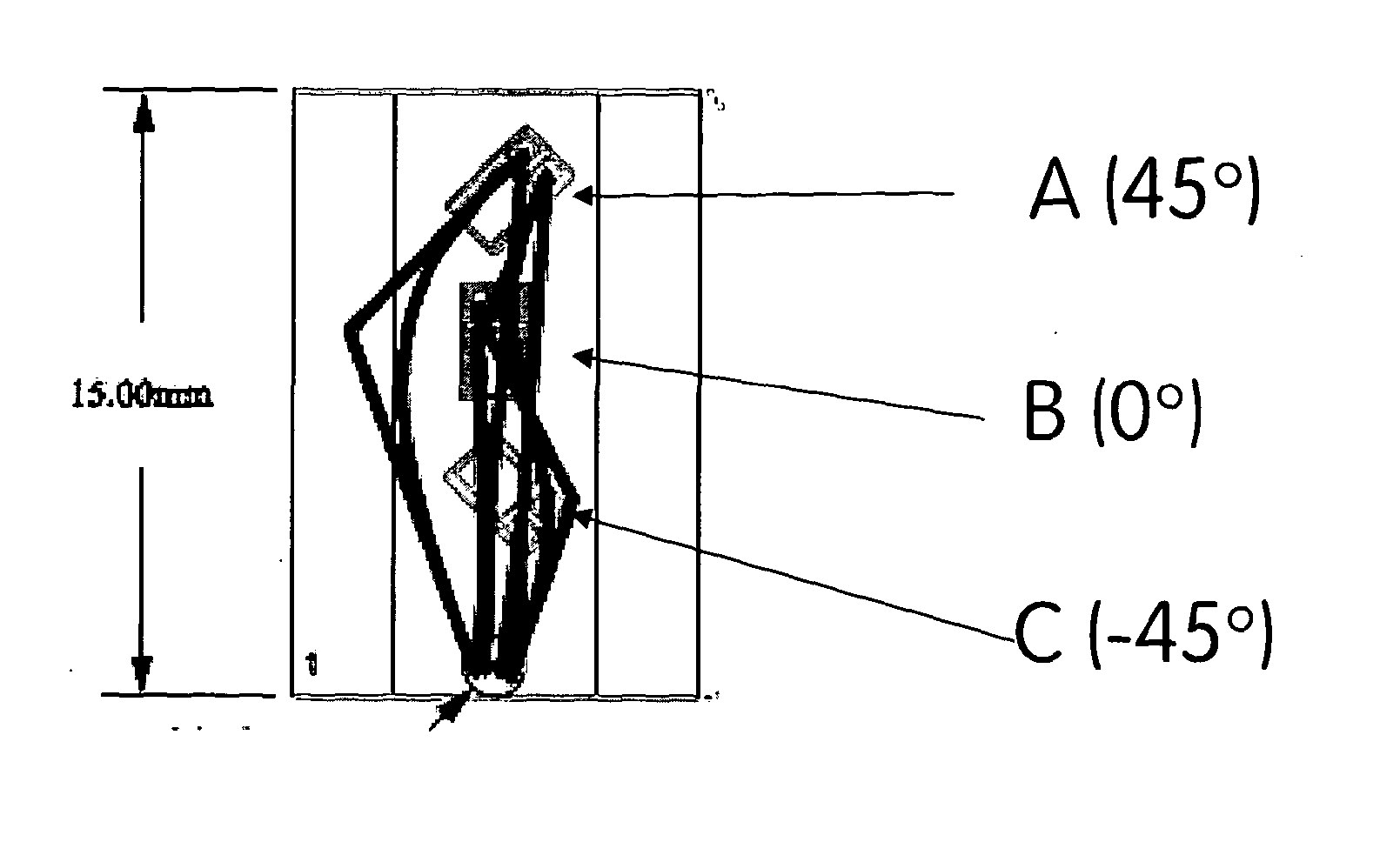
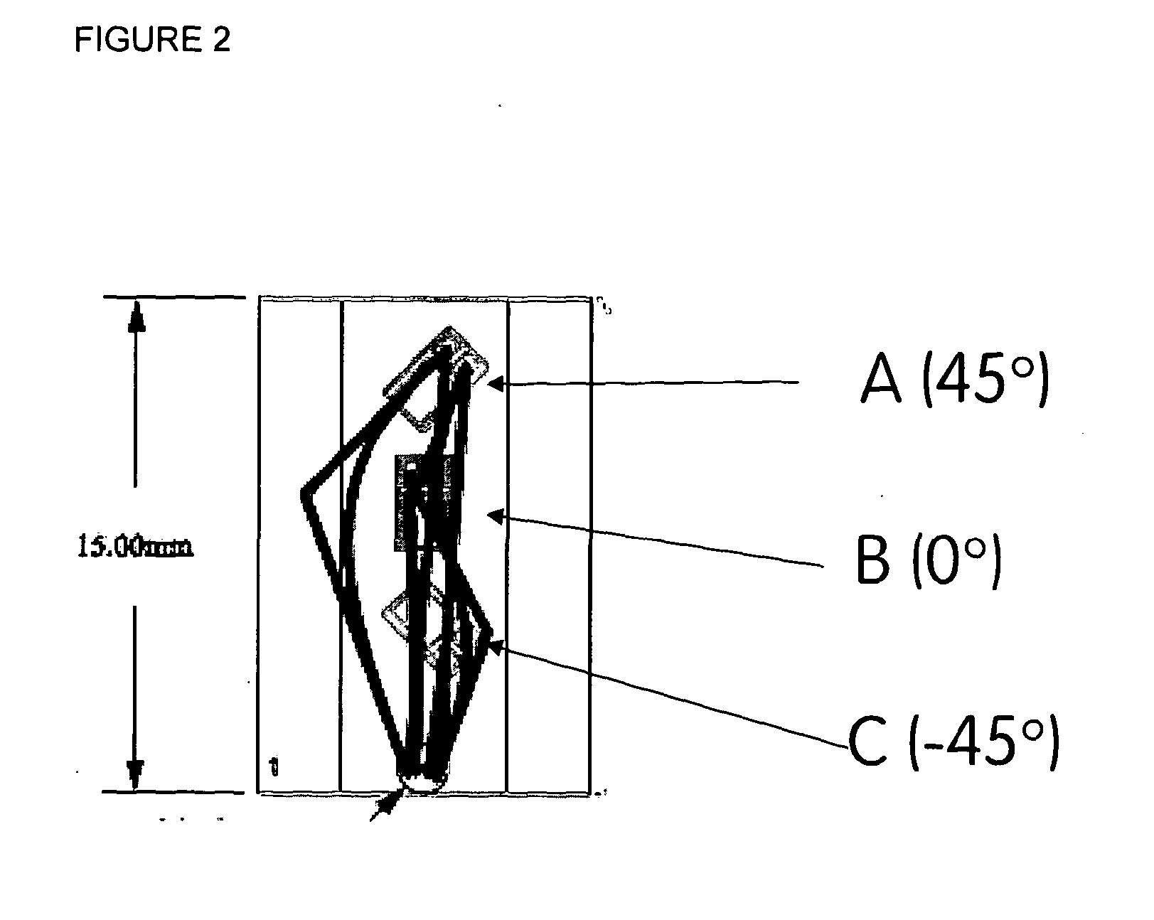
[0159]A “smart implant” is an implant that is able to sense its environment, apply intelligence to determine what action is required, and act on the sense information to change something in a controlled, beneficial manner. One attractive application of smart implant technology is to measure loads on an orthopaedic implant. For example, an IM nail is subjected to three types of loading: bending, torsional, and compression. These loads may be measured indirectly by measuring sensor output of a series of strain gauges mounted on the orthopaedic implant. In the case of an IM nail, diametrically apposed strain gauges mounted on the outer surfaces of the nail are subjected to tensile and compressive forces, respectively. Typically, the strain measured from the sensors is higher when the implant is loaded in bending rather than in compression.

[0160]A fundamental parameter of the strain gauge is its sensitivity to strain, expressed quantitatively as the gauge factor G, as defined in WO 2007...


PUM


Abstract

The invention relates generally to orthopaedic implants, and more particularly to orthopaedic implants having data acquisition capabilities and their use in monitoring and diagnosing fracture healing. RSA is also disclosed as a method for measuring inter-fragmentary movement in long bone fractures in order to confirm whether the fracture is reduced and for detecting changes in stiffness of the healing callus.

Description

CROSS REFERENCE TO RELATED APPLICATIONS[0001]This application claims the benefit of UK provisional application No. 0911697.1, filed on 6 Jul. 2009. The disclosure is herein incorporated, in its entirety, by reference.FIELD OF THE INVENTION[0002]The invention relates generally to orthopaedic implants, and more particularly to orthopaedic implants having data acquisition capabilities and their use in monitoring and diagnosing fracture healing.BACKGROUND TO THE INVENTION[0003]Fractures of long bones are a prevalent problem, accounting for 10% of non-fatal injuries in the USA (Kanakaris 2007). Of these, the most common are fractures of the tibial shaft, approximated to result in 77,000 hospitalisations a year in the USA (Schmidt et al 2003). The epidemiology and aetiology of tibial shaft fractures indicates a relation with risk behaviour. This type of fracture appears to be most prevalent in young men (Grutter 2000). A study by Court-Brown, 1995 found the mean age of patients with tibia...

Claims


Application Information

Patent Timeline
IPC IPC(8): A61B5/11G06K9/00A61B17/72
CPCA61B5/4504A61B5/6846A61B6/022A61F2002/4666A61B17/72A61B2017/00022A61B6/583A61B90/06A61F2/46A61B2090/064
Inventor WILSONTAYLOR, STEPHEN JAMES GUYMCCARTHY, IAN
Owner SMITH & NEPHEW INC
Why Eureka
Try Eureka