
Device for supporting a switch rail

a technology for switch rails and devices, applied in the direction of moving rail parts, railway tracks, ways, etc., can solve the problems of significantly lower required actuating force and save maintenance effort and costs, and achieve the effect of low cos

Active Publication Date: 2022-02-01
WIELAND AUSTRIA GES M B H
View PDF10 Cites 0 Cited by
  • Summary
  • Abstract
  • Description
  • Claims
  • Application Information

AI Technical Summary

Benefits of technology

The present invention offers a simplified and cost-effective device for supporting switch rails by extending the function of conventional bearings. The device includes a leaf spring that can be adjusted in its longitudinal direction in a guide body attached to the stock rail. This simplifies the design of the device and reduces the required actuating force, as compared to conventional bearings, which in turn reduces the actuating forces of the switch. The device is no longer need to be lubricated regularly, saving maintenance effort and costs. The adjustability of the position of the leaf spring bearing in the guide body allows for easy customization and high accuracy regardless of the position of the slide in the guide body.

Problems solved by technology

Furthermore, due to the lower rolling friction over the entire stroke, the required actuating force is considerably lower than with conventional bearings of switch tongues or switch rails.
This saves maintenance effort and costs.

Method used


Image

  • Device for supporting a switch rail
  • Device for supporting a switch rail
  • Device for supporting a switch rail

Examples


Embodiment Construction

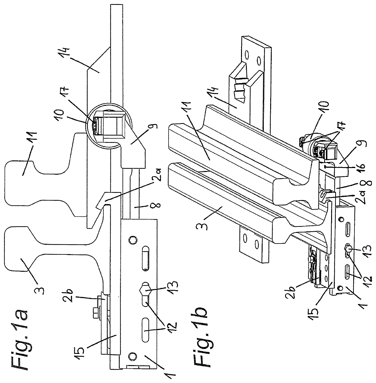
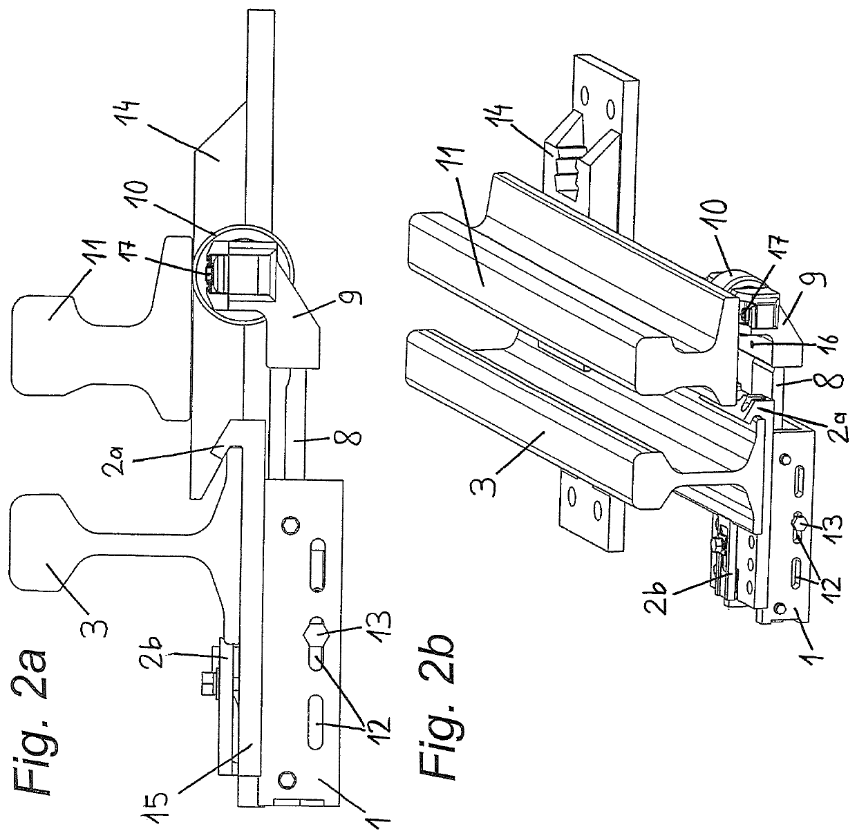
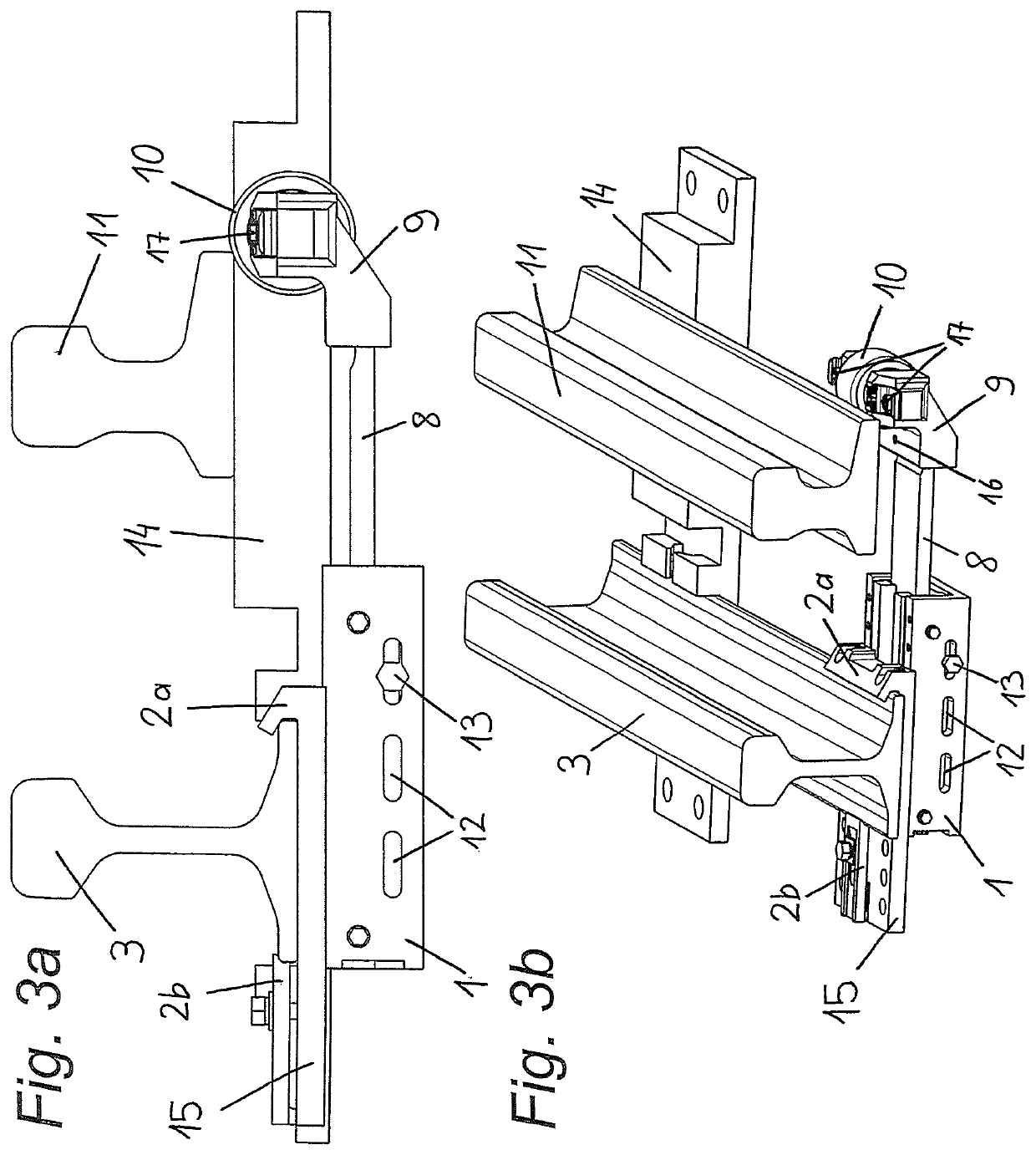
[0040]A guide body 1 is attached to a stock rail 3 via a clamp body 15 of a device according to the invention by means of clamps 2a, 2b. The guide body 1 is formed box-like in a U-shape and firmly connected to clamps 2a, 2b via a clamp body, wherein a rigid clamp 2a and a screw clamp 2b are provided. The rigid clamp 2a is arranged on the clamp body 15 to which a screw clamp 2b is screwed. The guide body 1 is screwed to the clamp body 15. Several holes are provided in both the clamp body 15 and the guide body 1 to allow mounting in various positions along a longitudinal axis of the guide body 1.

[0041]In the guide body 1 there is a slide 4, which in turn can be moved and fastened longitudinally within the guide body 1. For this purpose, there are elongated holes 12 on one side wall of the guide body 1 to fix the slide 4 with a screw 13. A rack 5 is provided on the inner wall of the guide body 1 to lock the position of the slide 4. Rack pieces 6 engaging in the rack 5 are arranged on t...


PUM


Abstract

The invention relates to supporting a switch rail of a switch having a projecting leaf spring which can be pretensioned to the switch rail and on which the switch rail is displaceably arranged. Low friction and easy adaptation to the mounting position is possible in that the leaf spring is adjustably arranged in its longitudinal direction in a guide body which can be fastened to the stock rail.

Description

CROSS-REFERENCE TO RELATED APPLICATIONS[0001]This application is a national stage filing based upon International PCT Application No. PCT / AT2017 / 060306, filed 21 Nov. 2017, which claims the benefit of priority to Austria application No. A 51060 / 2016, filed 23 Nov. 2016.BACKGROUND[0002]The invention relates to a device for supporting a switch rail of a switch having a projecting leaf spring which is pretensioned to the switch rail and on which the switch rail is displaceably arranged.[0003]Conventional switches for rail vehicles usually have slidingly mounted rail tongues. When the switch position is adjusted, considerable actuating forces thus occur. Due to necessary lubrication, the surrounding substrate is contaminated and regular application of lubricant is necessary. In the case of switches without switching aids, the sliding surfaces are lubricated by hand to ensure secure operation. This regularly results in an increased logistical effort. In addition, there is always a residu...

Claims


Application Information

Patent Timeline
IPC IPC(8): E01B7/02
CPCE01B7/02E01B2202/044E01B2202/046E01B7/20E01B7/26
Inventor REISER, GEORGREISER, RUDOLFKAINZ, MICHAELKOLLOUCH, ROBERT
Owner WIELAND AUSTRIA GES M B H
Learn More