
Binding machine

a technology of a binding machine and a ring, which is applied in the direction of building construction, building material handling, construction, etc., can solve the problems of adversely affecting the braking operation and the failure of the operation, and achieve the effect of ensuring the operation of the reel brak

Active Publication Date: 2022-02-01
MAX CO LTD
View PDF15 Cites 0 Cited by
  • Summary
  • Abstract
  • Description
  • Claims
  • Application Information

AI Technical Summary

Benefits of technology

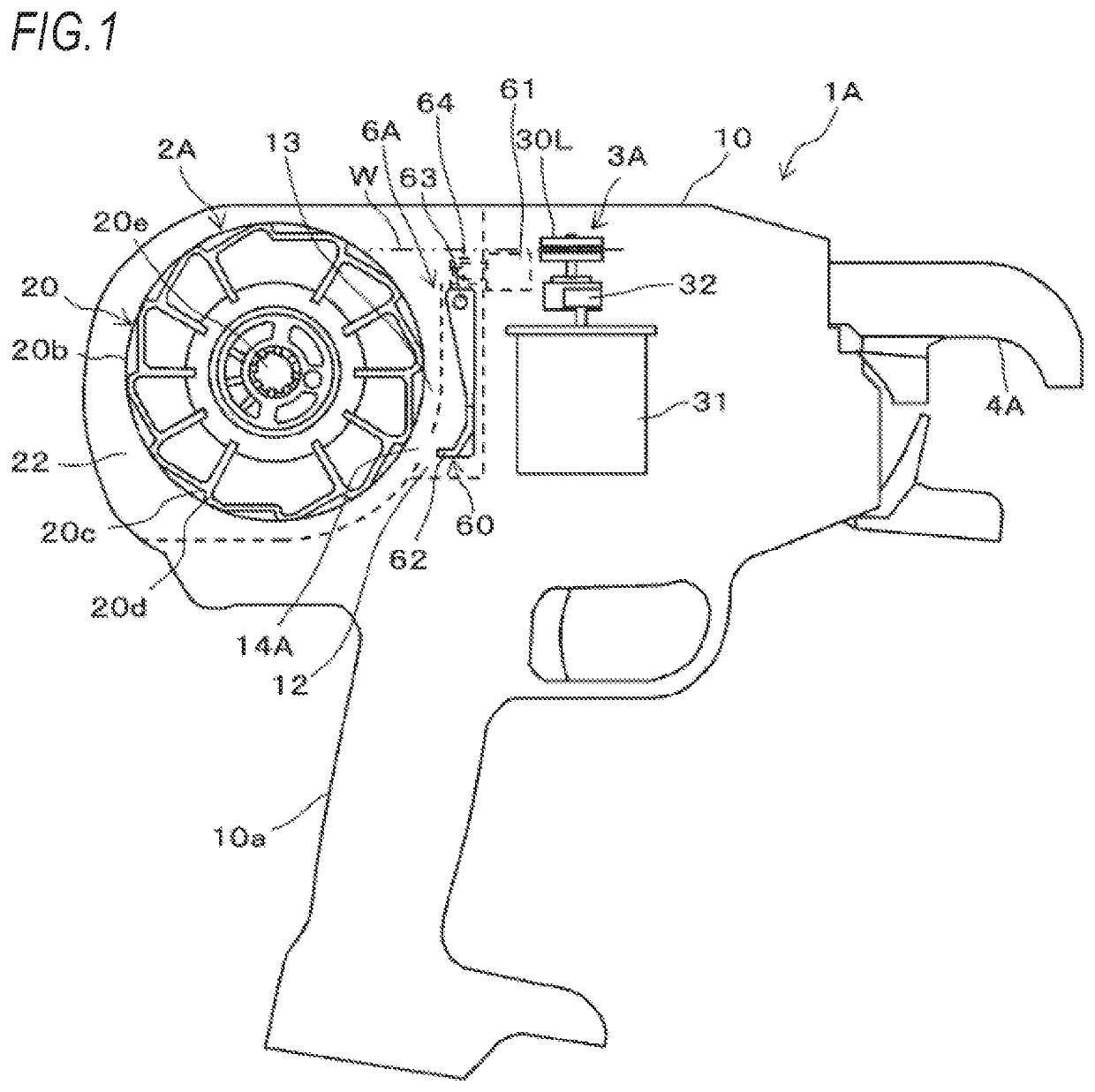
[0007]The present disclosure is made to solve such problems and an object thereof is to provide a binding machine which can discharge debris that enters a brake accommodating portion when the brake accommodating portion is provided to cover the periphery of a stopper lever or the like or a binding machine which prevents debris from entering a brake accommodating portion even when the brake accommodating portion is provided to cover the periphery of a stopper lever or the like.
[0012]According to the disclosure, the foreign matter which enters the brake accommodating portion may be discharged to the outside, so the operability of the reel brake may be secured.
[0013]Further, according to the disclosure, it is possible to suppress the entry of the foreign matter into the brake accommodating portion through the third opening portion, so the operability of the reel brake may be secured.

Problems solved by technology

In the configuration in which the stopper lever or the like is exposed to the reel accommodating portion, rainwater or the like easily adheres to the stopper lever or the like, which causes rust and is also a cause of operational failure.
However, by providing the brake accommodating portion, debris such as pieces of the wire reel may be accumulated in the brake accommodating portion, which may adversely affect a braking operation.

Method used


Image

  • Binding machine
  • Binding machine
  • Binding machine

Examples


first embodiment

[0065]Example of Brake Accommodating Portion of First Embodiment

[0066]FIGS. 5, 6A, 6B, 7A, 7B, 8A, 8B, and 9 are views illustrating an example of a brake accommodating portion of a first embodiment provided in the reinforcing bar binding machine of the embodiment. In the brake accommodating portion 12 (12A1 to 12A5) of each example of the first embodiment, foreign matter Du which enters from the first opening portion 14A to the brake accommodating portion 12 (12A1 to 12A5) is removed through a second opening (68A1 to 68A5).

[0067]As illustrated in FIG. 5, the brake accommodating portion 12A1 according to the first example of the first embodiment includes the second opening portion 68A1 which communicates the inside of the brake accommodating portion 12A1 with the outside of the brake accommodating portion 12A1 excluding the reel accommodating portion 2A. The second opening portion 68A1 has an opening of a size that can discharge the foreign matter Du. The second opening portion 68A1 ...

second embodiment

[0089]Example of Brake Accommodating Portion of Second Embodiment

[0090]FIGS. 13 to 16 are configuration diagrams illustrating an example of a brake accommodating portion of a second embodiment provided in the reinforcing bar binding machine of the embodiment. In the brake accommodating portion 12 (12B1 to 12B4) of each example of the second embodiment, the embodiment prevents an entry of the foreign matter Du into the brake accommodating portion 12 through a third opening 14B communicating the reel accommodating portion 2A with the brake accommodating portion 12 (12B1 to 12B4).

[0091]As illustrated in FIG. 13, the brake accommodating portion 12B1 of a first example of the second embodiment has a sealing member 66B1 at the third opening portion 14B provided in the moving path of the engaging portion 62. The sealing member 66B1 is an example of a shielding portion and has a member such as rubber capable of expanding or contracting by elastic deformation, a member capable of expanding o...


PUM


Abstract

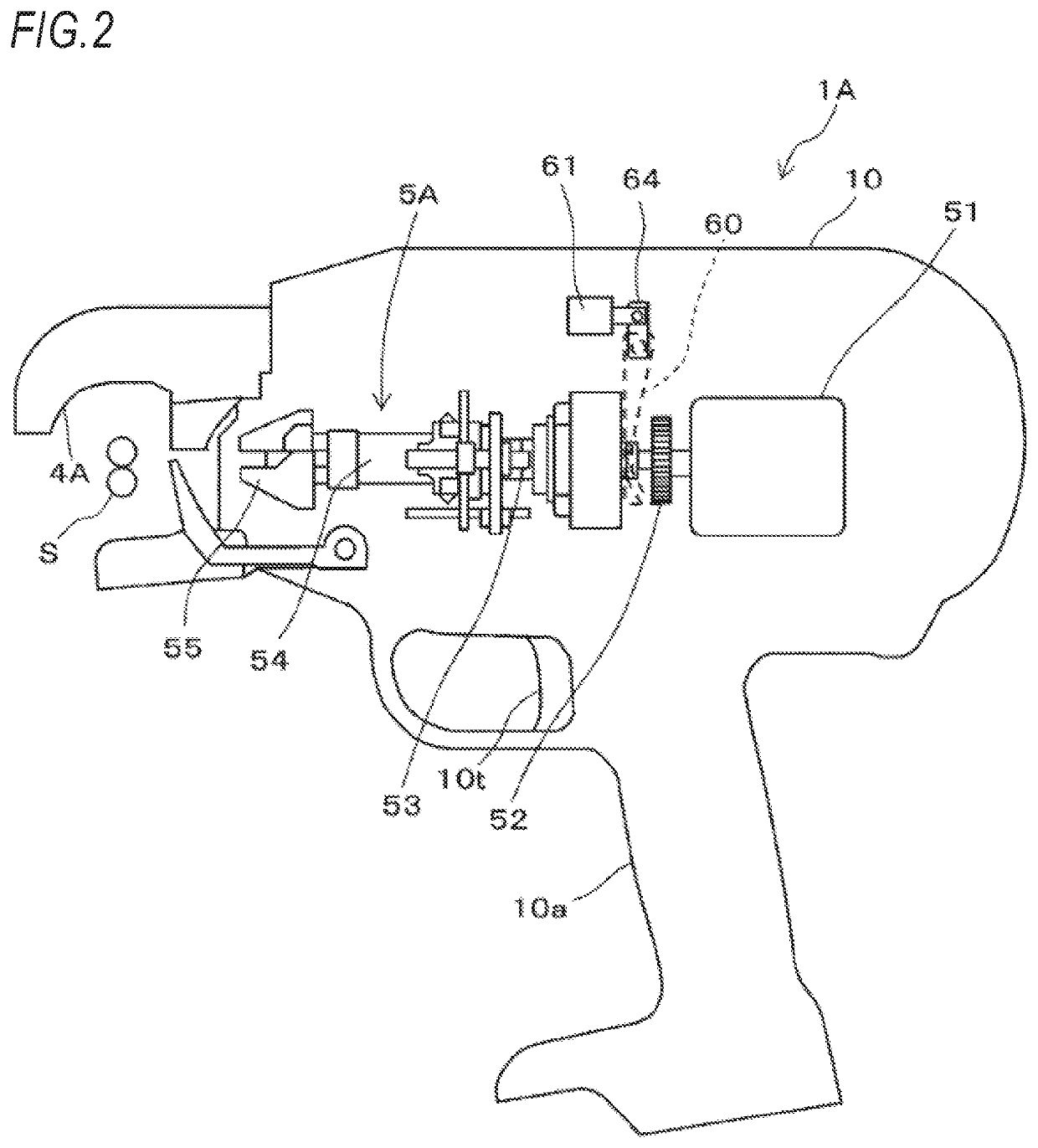
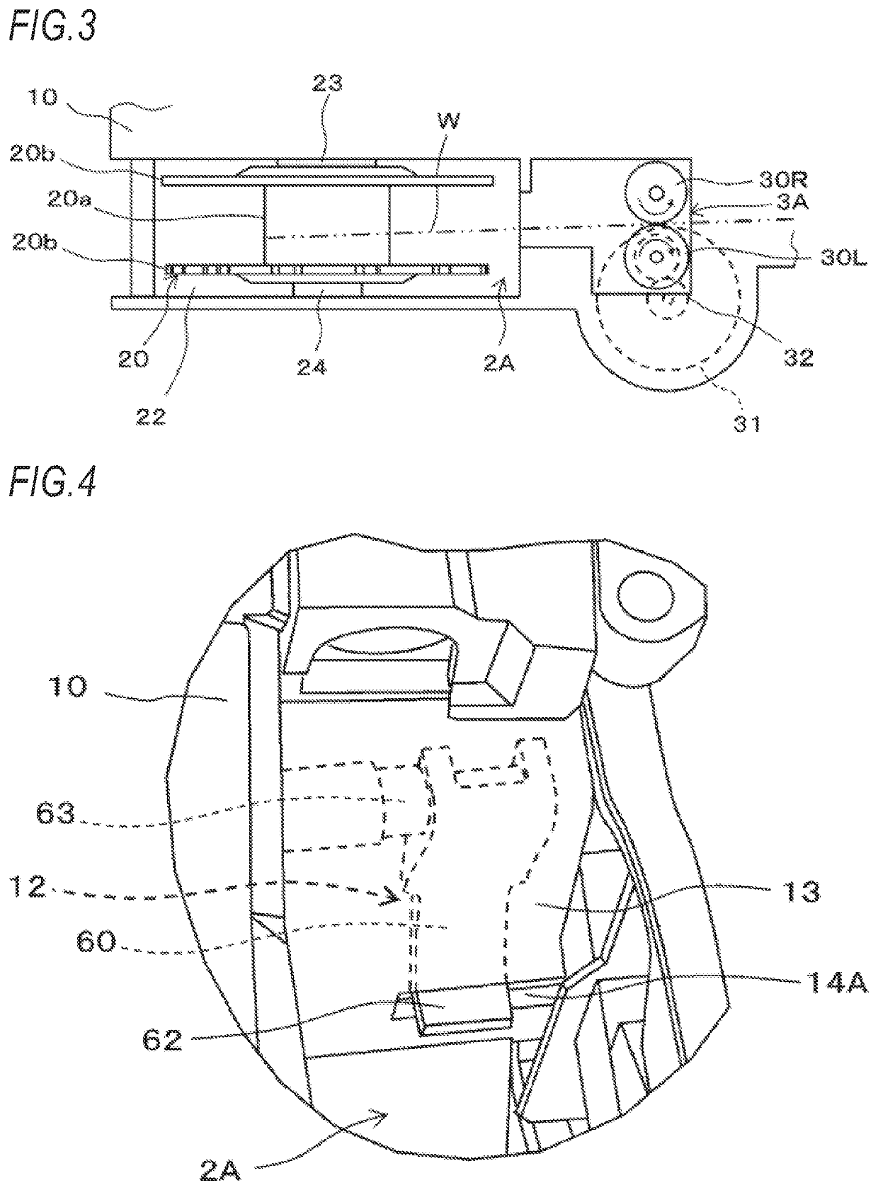
A binding machine includes a reel accommodating portion, a reel brake, and a brake accommodating portion. The reel accommodating portion is configured to rotatably accommodate a wire reel. The reel brake has an engaging portion which is configured to engage with the wire reel and is configured to brake rotation of the wire reel. The brake accommodating portion covers a periphery of the reel brake except at least the engaging portion. The brake accommodating portion includes a first opening portion exposing the engaging portion and a second opening portion communicating with an outside.

Description

CROSS-REFERENCE TO RELATED APPLICATIONS[0001]This application is based on and claims priority to Japanese Patent Application No. 2018-125603 filed on Jun. 29, 2018, the disclosure of which is incorporated herein in its entirety by reference, and priority is claimed to the foregoing.TECHNICAL FIELD[0002]The present disclosure relates to a binding machine for binding a binding target material such as a reinforcing bar with a wire.BACKGROUND ART[0003]In recent years, there is a binding machine called a “reinforcing bar binding machine”, in which a wire is wound around a plurality of reinforcing bars and the plurality of reinforcing bars are bound by twisting the wire.[0004]In the related art, in this kind of reinforcing bar binding machine, a wire wound around a wire reel is fed toward a tip end side of a binding machine body by a feeding mechanism including a pair of feed gears and the like and the fed wire is curled by a curl guide provided on the tip end side of the binding machine ...

Claims


Application Information

Patent Timeline
Patent Type & Authority Patents(United States)
IPC IPC(8): E04G21/12
CPCE04G21/123
Inventor KAWAZOE, AKIRA
Owner MAX CO LTD
Learn More