
Rotation angle detecting device

a detection device and rotating angle technology, applied in the direction of measurement devices, measurement apparatus components, instruments, etc., can solve the problems of increasing the cost of parts, increasing the overall cost, and increasing the assembly cost of parts

Active Publication Date: 2015-04-07
NIPPON SEIKI CO LTD
View PDF15 Cites 0 Cited by
  • Summary
  • Abstract
  • Description
  • Claims
  • Application Information

AI Technical Summary

Benefits of technology

The present invention provides a rotation angle detecting device that prevents the filling member from entering the space where the magnet is located. This helps to improve the functionality and accuracy of the device.

Problems solved by technology

Since the rotation angle detecting device described in Patent Document 1 includes the housing which rotatably supports the rotation member serving as the rotation shaft and the cover accommodating the magneto-electric conversion element, the rotation angle detecting device has the problem in that the number of parts constituting the device is increased to require higher assembly cost and parts cost to result in an increase in the overall cost.

Method used


Image

  • Rotation angle detecting device
  • Rotation angle detecting device

Examples


Embodiment Construction

[0020]An embodiment of the present invention will hereinafter be described with the accompanying drawings.

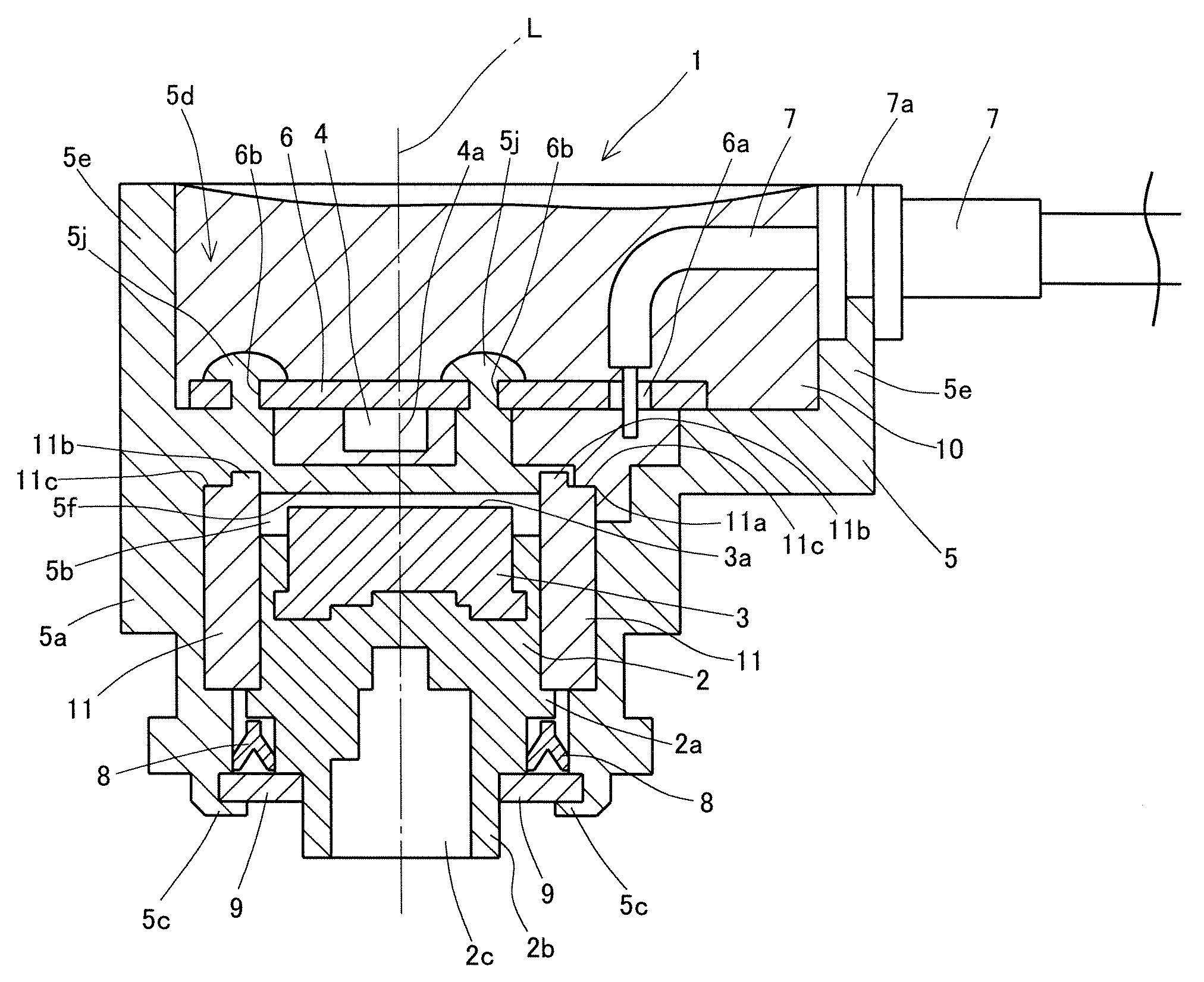
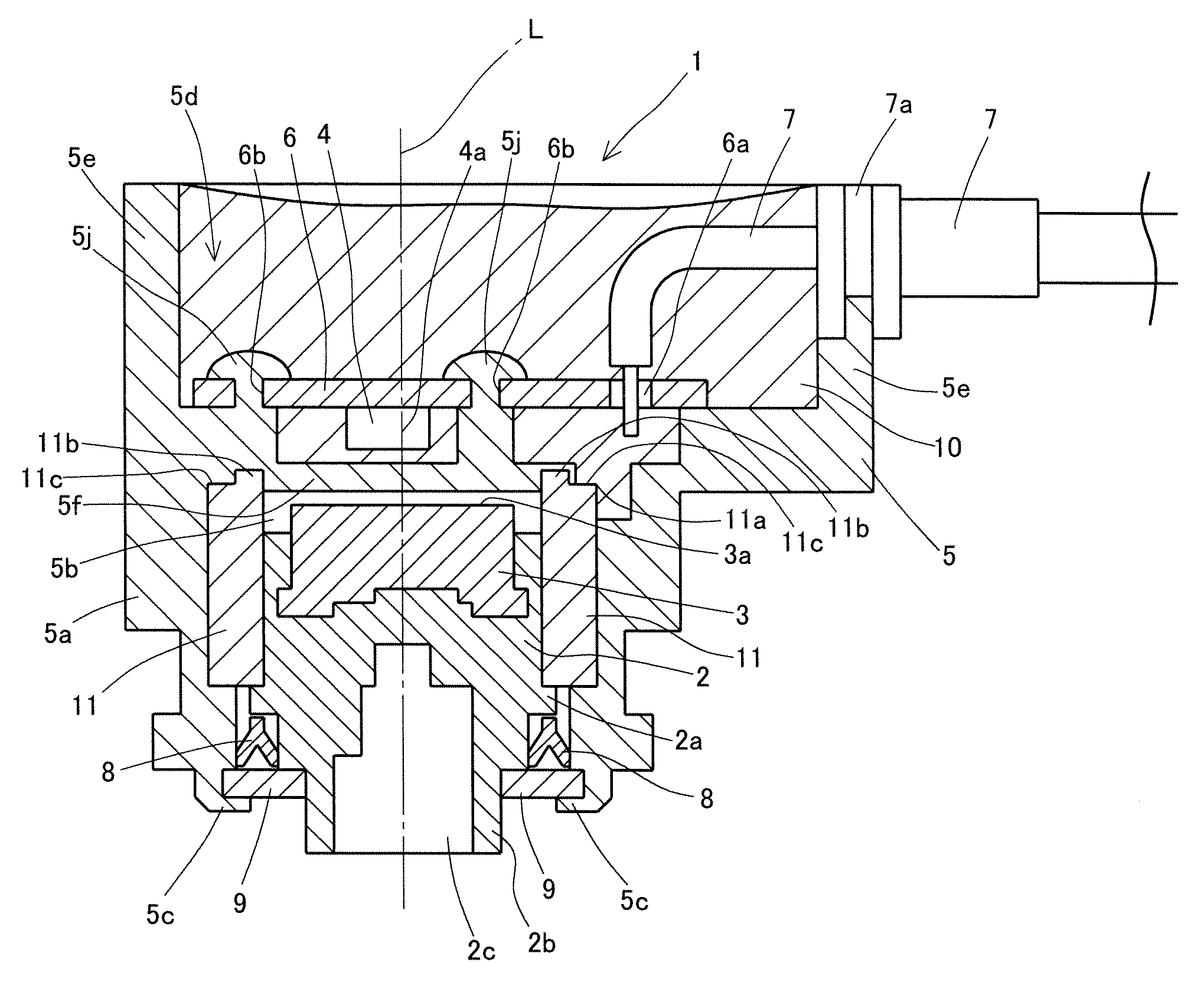
[0021]A rotation angle detecting device 1 according to the present embodiment is formed mainly of a rotation member 2, a magnet 3, a magnetism detecting package 4 containing a magneto-electric conversion element 4a, a housing 5, a circuit board 6, and a wiring 7. L indicates a rotation axis of the rotation member 2 and the magnet 3.

[0022]The rotation member 2 rotates with an object under detection coupled thereto and is made of a synthetic resin material such as polyacetal.

[0023]The rotation member 2 has a generally cylindrical shape and has a flange portion 2a without any breaks on the periphery. The rotation member 2 includes a hermetic member, later described, below the flange portion 2a in FIG. 1. The rotation member 2 also includes a small-diameter portion 2b having a smaller diameter below the hermetic member. The small-diameter portion 2b is provided with a depression por...


PUM


Abstract

Disclosed is a rotation angle detecting device wherein a filling member applied in a second housing section which houses an electromagnetic conversion element is prevented from entering a first housing section which houses a magnet. The rotation angle detecting device (1) is provided with: a rotating member (2); the magnet (3), which is fixed to the rotating member (2) and rotates with the rotation of the rotating member (2); a magnetism detecting package (4) that houses an electromagnetic conversion element (4a), which is disposed to face the magnet (3), and detects the intensity of the magnetic field of the magnet (3) by means of rotation of the magnet (3); a housing (5) having a first housing section (5b) that rotatably houses the rotating member (2), and a second housing section (5d) that houses the magnetism detecting package (4), with a partition (5f) as a reference; a filling member (10), with which the second housing section (5d) is filled such that the magnetism detection package (4) is hermetically housed and held; and a cylindrical metal member (11), which is provided in the first housing section (5b) such that the rotating member (2) is rotatably supported and a part (11a) of the metal member is exposed to the second housing section (5d).

Description

RELATED APPLICATIONS[0001]This application is the U.S. National Phase under 35 U.S.C.§371 of International Application No. PCT / JP2010 / 066028, filed on Sep. 16, 2010, which in turn claims the benefit of Japanese Application No. 2009-227390, filed on Sep. 30, 2009, the disclosures of which Applications are incorporated by reference herein.TECHNICAL FIELD[0002]The present invention relates to a rotation angle detecting device for detecting the rotation angle of an object under detection.BACKGROUND ART[0003]Known conventional rotation angle detecting devices include a throttle position sensor which detects the rotation angle of a shaft of a throttle valve (that is, the open / close angle of the throttle valve) when the shaft is rotated in association with the open / close operation of the throttle valve placed within an aspiration path of an internal combustion engine (see, for example, Patent Document 1).[0004]The rotation angle detecting device realized by the throttle position sensor des...

Claims


Application Information

Patent Timeline
Patent Type & Authority Patents(United States)
IPC IPC(8): G01B7/30G01D5/14G01D11/24
CPCG01D5/145G01D11/245
Inventor IWAHASHI, MASARU
Owner NIPPON SEIKI CO LTD
Learn More