
Fuel gas supply system and method of ship

a fuel gas supply system and ship technology, applied in the direction of motor-driven power plants, vessel construction, marine propulsion, etc., can solve the problems of increasing the cost of complying with such regulations, and the risk of explosion of both devices, so as to facilitate the supply of fuel gas, reduce the risk of explosion, and save space in the ship

Active Publication Date: 2017-08-22
DAEWOO SHIPBUILDING & MARINE ENG CO LTD
View PDF30 Cites 0 Cited by
  • Summary
  • Abstract
  • Description
  • Claims
  • Application Information

AI Technical Summary

Benefits of technology

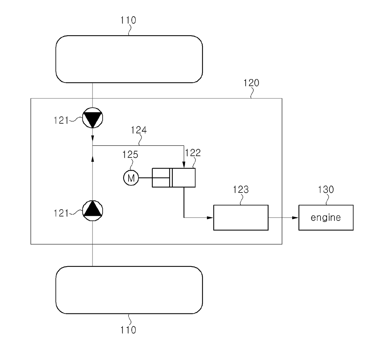
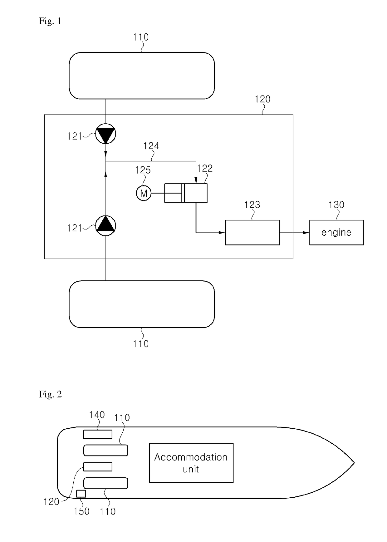
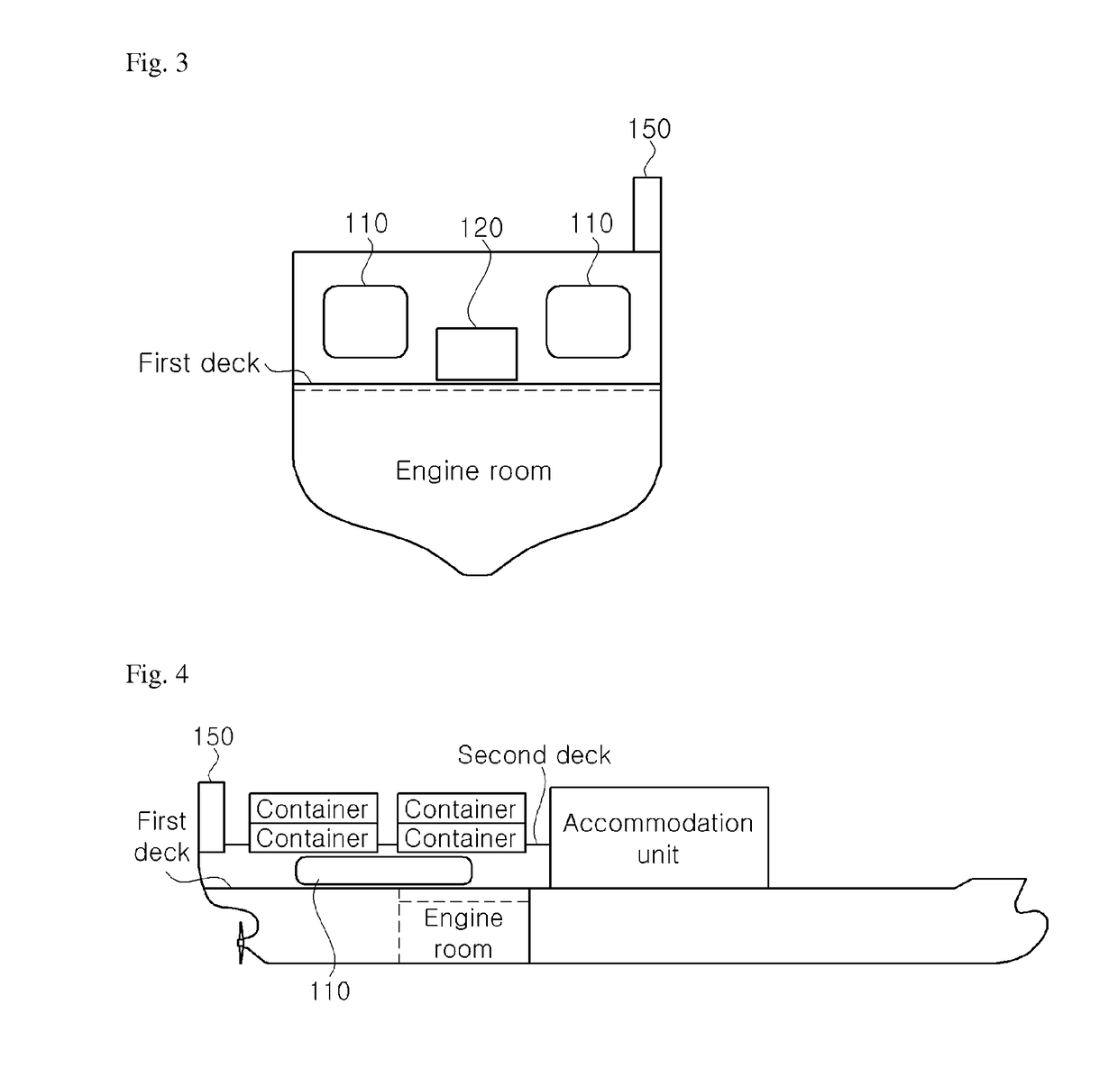
The invention is of a ship design that reduces the risk of explosions due to fuel gas. It includes a bunkering manifold at the stern of the ship for easy supply of fuel gas, and a vent riser at the stem of the ship to prevent fuel gas from approaching non-hazardous cargo like a cooling container. The bunkering manifold and vent riser can be placed on opposite sides of the ship, minimizing the risk of explosion. Additionally, an FGS room and fuel gas tank are placed above the engine room to maximize space usage and minimize the length of the fuel gas supply line. The fuel gas tank is also placed longitudinally to minimize sloshing. Overall, the invention ensures safety and efficiency in ship design.

Problems solved by technology

In recent years, with increasing interest in environmental pollution due to various toxic materials contained in exhaust gas generated upon combustion of heavy oil, marine diesel oil (MDO), and the like used as fuel for various ship engines, regulation has been intensified with regard to ship engines using heavy oil and the like as fuel, thereby causing increase in costs to comply with such regulations.
Thus, it is an important issue to determine suitable locations of the fuel gas tank and the FGS room in a ship in order to achieve efficient use of a space in the ship.
Since the bunkering manifold acts as a device for receiving the fuel gas, and the vent riser discharges BOG, both devices are exposed to a risk of explosion.

Method used


Image

  • Fuel gas supply system and method of ship
  • Fuel gas supply system and method of ship
  • Fuel gas supply system and method of ship

Examples


Embodiment Construction

[0049]Embodiments of the present invention will now be described in detail with reference to the accompanying drawings. It should be noted that like components are denoted by like reference numerals throughout the specification and the accompanying drawings. In addition, descriptions of functions or features irrelevant to the present invention will be omitted for clarity.

[0050]The International Maritime Organization regulates emission of nitrogen oxides (NOx) and sulfur oxides (SOx) among exhaust gas of ships, and plans additional regulation on carbon dioxide (CO2) in recent years. Particularly, compulsory fulfillment of the regulations on emission of nitrogen oxides (NOx) and sulfur oxides (SOx) took effect in May 2005 after a long duration of eight years from suggestion of the regulations by the protocol of the Prevention of Marine Pollution from Ships in 1997.

[0051]Accordingly, various methods for reducing emission of nitrogen oxides (NOx) have been suggested in order to satisfy ...


PUM


Abstract

Disclosed herein is arrangement of a fuel gas tank in a fuel gas supply system that supplies liquefied natural gas to an engine. In accordance with one aspect of the invention, a fuel gas supply system of a ship includes an engine generating driving force using fuel gas; and a fuel gas tank storing the fuel gas to be supplied to the engine, wherein the engine is disposed in an engine room placed at the stern of the ship and the fuel gas tank is disposed above the engine room.

Description

TECHNICAL FIELD[0001]The present invention relates to a fuel gas supply system and method of a ship, and more particularly, to arrangement of a bunkering manifold, a vent riser, a fuel gas supply (FGS) room and a fuel gas tank in a fuel gas supply system which supplies liquefied natural gas to a ship engine.BACKGROUND ART[0002]In recent years, with increasing interest in environmental pollution due to various toxic materials contained in exhaust gas generated upon combustion of heavy oil, marine diesel oil (MDO), and the like used as fuel for various ship engines, regulation has been intensified with regard to ship engines using heavy oil and the like as fuel, thereby causing increase in costs to comply with such regulations.[0003]Accordingly, development of ships using clean gas fuel such as LNG, LPG, CNG or DME has been suggested and achieved in addition to the prevention or minimization of use of fuel oil such as heavy oil or MDO.[0004]Particularly, an M-type electronically contr...

Claims


Application Information

Patent Timeline
Patent Type & Authority Patents(United States)
IPC IPC(8): B63B11/04B63H21/38F02M21/02B63B17/00B63H21/14
CPCB63H21/38B63B11/04B63B17/0036B63H21/14F02M21/0221F02M21/0293Y02T10/32Y02T70/5218Y02T10/30F02M21/02
Inventor LEE, JOON CHAEKANG, DONG EOKPARK, CHEONG GI
Owner DAEWOO SHIPBUILDING & MARINE ENG CO LTD
Learn More