Supercharge Your Innovation With Domain-Expert AI Agents!

Hot metal supply injection method and hot metal supply injection device

a technology of injection device and hot metal, which is applied in the direction of molten metal supply equipment, casting apparatus, manufacturing tools, etc., can solve the problems of not being configured to enable such utilization technically, and difficulty in handling low-viscosity molten metal, etc., and achieve the effect of restricting molten metal

Active Publication Date: 2022-02-08
TOYOTA JIDOSHA KK
View PDF3 Cites 0 Cited by
  • Summary
  • Abstract
  • Description
  • Claims
  • Application Information

AI Technical Summary

Benefits of technology

The invention aims to prevent molten metal from leaking out of a container. The design uses a negative pressure to hold the metal in place, and the container has a unique design that prevents the metal from spilling out even at various angles. The interior of the container can be filled with the metal without it spilling out. The patent also describes how the outer plunger tip can be moved to fill the cavity of a mold with the metal.

Problems solved by technology

In this hot metal supply injection method, when the injection sleeve is put down horizontally, molten metal may spill out from an end portion of the injection sleeve.
Therefore, it is difficult to handle low-viscosity molten metal.
This hot metal supply injection method is designed to allow utilization of semi-molten metal with high liquid-phase ratio as well, but is considered not to be configured to enable such utilization technically.

Method used


Image

  • Hot metal supply injection method and hot metal supply injection device
  • Hot metal supply injection method and hot metal supply injection device
  • Hot metal supply injection method and hot metal supply injection device

Examples


first embodiment

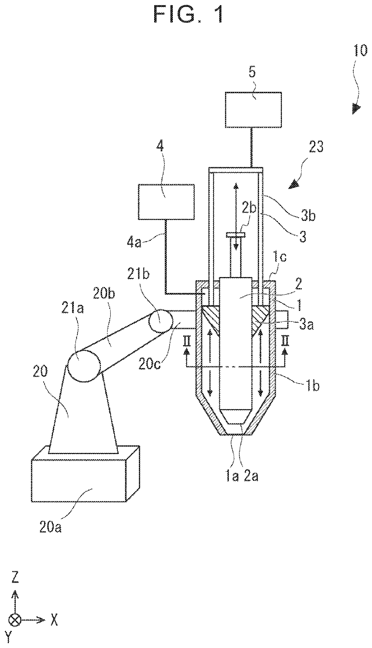
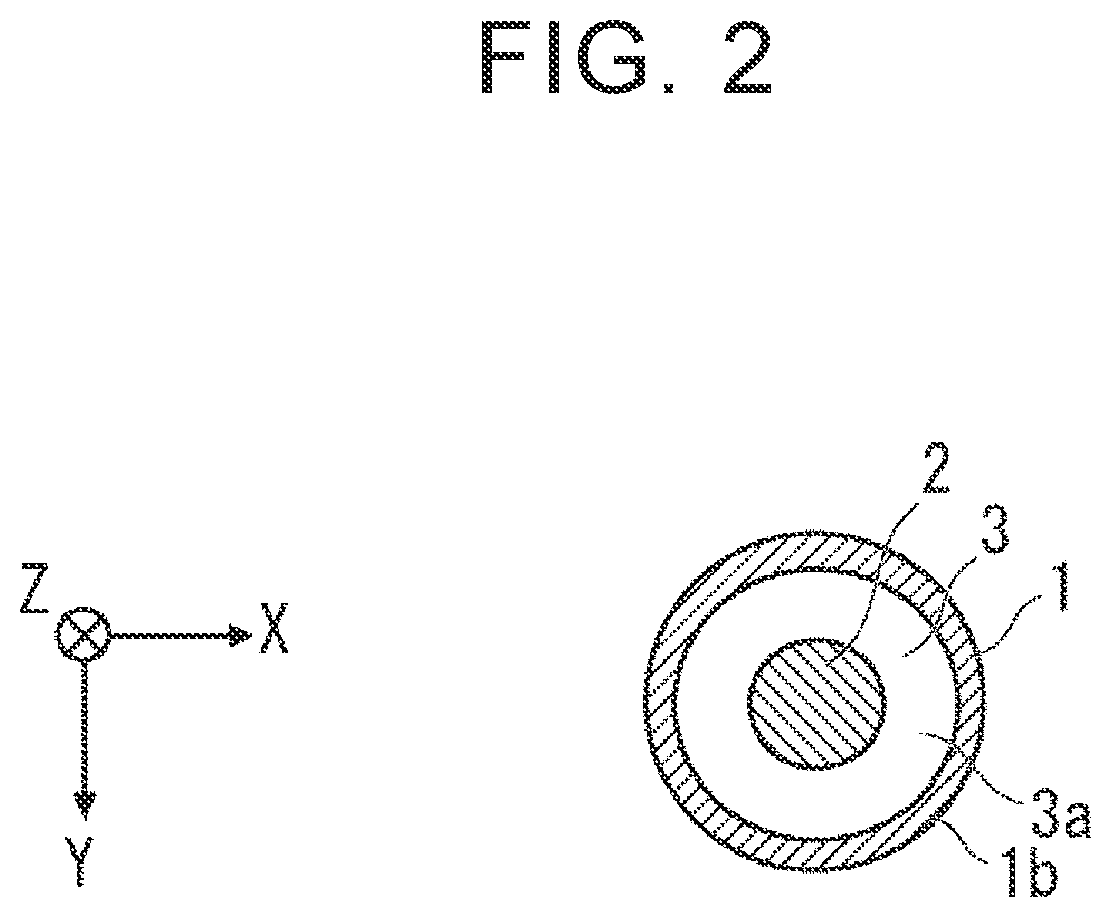
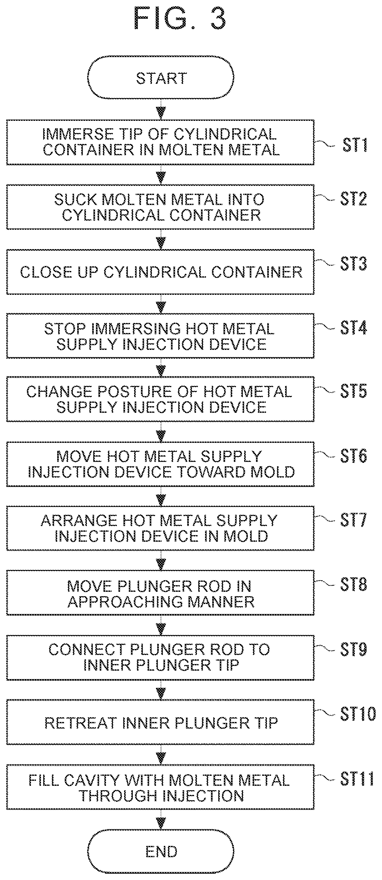
[0027]A hot metal supply injection method according to the first embodiment will be described with reference to FIGS. 1 to 9. FIG. 1 is a schematic view showing a casting device that can be used in the hot metal supply injection method according to the first embodiment. FIG. 2 shows a cross-section of an essential part of the casting device shown in FIG. 1. FIG. 3 is a flowchart showing the hot metal supply injection method according to the first embodiment. FIGS. 4 to 8 are schematic views each showing a plurality of steps in the hot metal supply injection method according to the first embodiment. FIG. 9 is a schematic view showing one step in the hot metal supply injection method according to the first embodiment. Incidentally, for the sake of understandability, a negative pressure generation device 4, a moving device 5, a robot arm 20, and the like that will be described later are omitted in FIGS. 5 to 9.

[0028]Incidentally, as a matter of course, a right-hand XYZ coordinate syste...


PUM

PropertyMeasurementUnit
pressureaaaaaaaaaa
viscosityaaaaaaaaaa
solid-phase ratioaaaaaaaaaa

Abstract

A hot metal supply injection method includes generating a negative pressure in a cylindrical container by a negative pressure generation device, and causing molten metal to be sucked into the cylindrical container from a retention furnace, while keeping an opening portion of the cylindrical container immersed in the molten metal, arranging the opening portion of the cylindrical container in a gate of a cavity while holding the negative pressure by closing up the opening portion of the cylindrical container after moving an inner plunger tip to a tip side of the cylindrical container, and moving the inner plunger tip to a rear end side of the cylindrical container, then moving an outer plunger tip, together with the inner plunger tip, to the tip side of the cylindrical container, and filling the interior of the cavity with the molten metal through injection via the gate.

Description

CROSS-REFERENCE TO RELATED APPLICATION[0001]This application claims priority to Japanese Patent Application No. 2020-018018 filed on Feb. 5, 2020, incorporated herein by reference in its entirety.BACKGROUND1. Technical Field[0002]The disclosure relates to a hot metal supply injection method and a hot metal supply injection device, and more specifically, to a hot metal supply injection method and a hot metal supply injection device for supplying and injecting molten metal.2. Description of Related Art[0003]In a hot metal supply injection method disclosed in Japanese Unexamined Patent Application Publication No. 09-192811 (JP 09-192811 A), semi-molten metal is supplied to a vertically erected injection sleeve. After that, the injection sleeve is put down horizontally and connected to a die-casting machine, and the semi-molten metal in the sleeve is pressed into a mold.SUMMARY[0004]The inventors of the disclosure of the present application have found the following problem. In this hot ...

Claims


Application Information

Patent Timeline
Patent Type & Authority Patents(United States)
IPC IPC(8): B22D17/14B22D17/20B22D17/30
CPCB22D17/14B22D17/203B22D17/2023B22D17/30B22D17/007B22D18/04B22D18/02B22D39/06B22D39/026
Inventor SOTOZAKI, SHUJI
Owner TOYOTA JIDOSHA KK
Features
  • R&D
  • Intellectual Property
  • Life Sciences
  • Materials
  • Tech Scout
  • Unparalleled Data Quality
  • Higher Quality Content
  • 60% Fewer Hallucinations
Learn More