Method and device for detecting collisions for a vehicle

a collision detection and vehicle technology, applied in control devices, external condition input parameters, instruments, etc., can solve the problems of increasing the probability of the second collision, generating a collision-free trajectory, and not being able to refer merely to rectangular bounding boxes

Active Publication Date: 2022-02-08
ROBERT BOSCH GMBH
View PDF14 Cites 0 Cited by
  • Summary
  • Abstract
  • Description
  • Claims
  • Application Information

AI Technical Summary

Benefits of technology

[0012]Thus, in accordance with the present invention, a method and a device for detecting collisions for a vehicle are provided, an entire swath of the vehicle being continuously checked for collision. The need is thereby eliminated for discretizing the path, thus the trajectory, and for the repeated discreet checking of individual configurations for collision. Thus, a method is provided which requires very little computing time and only minor computational resources. Thus, in the case of an RRT, a computing speed may be nearly doubled.
[0021]It is also advantageous when the first collision check is initially performed, then the second collision check, and then the third collision check for all of the relatively near sections until a collision is detected in one of the second or third collision checks. The second and third collision checks are performed in response to no collision being detected in any of the first collision checks. Thus, the first collision check is initially performed for all sections of the trajectory. If no collision is detected, the second collision check is then carried out for the sections. If a collision is already thereby detected, this eliminates the need for the third collision check, respectively for the remaining second collision checks. If all of the second collision checks were performed without a collision being detected, the third collision checks are executed.

Problems solved by technology

The difficulty first lies in generating a collision-free trajectory that includes as few as possible changes in direction and minimal curvature changes over the course of the trajectory.
Moreover, in such scenarios, the exact contour of the vehicle must be included in the planning, and it is not possible to refer merely to rectangular bounding boxes or circles on the contour to actually be able to find a trajectory of adequate quality that includes few changes of direction.
This increases the probability of the second collision check already correctly detecting whether a collision will occur between the vehicle and an object.

Method used


Image

  • Method and device for detecting collisions for a vehicle
  • Method and device for detecting collisions for a vehicle
  • Method and device for detecting collisions for a vehicle

Examples


Embodiment Construction

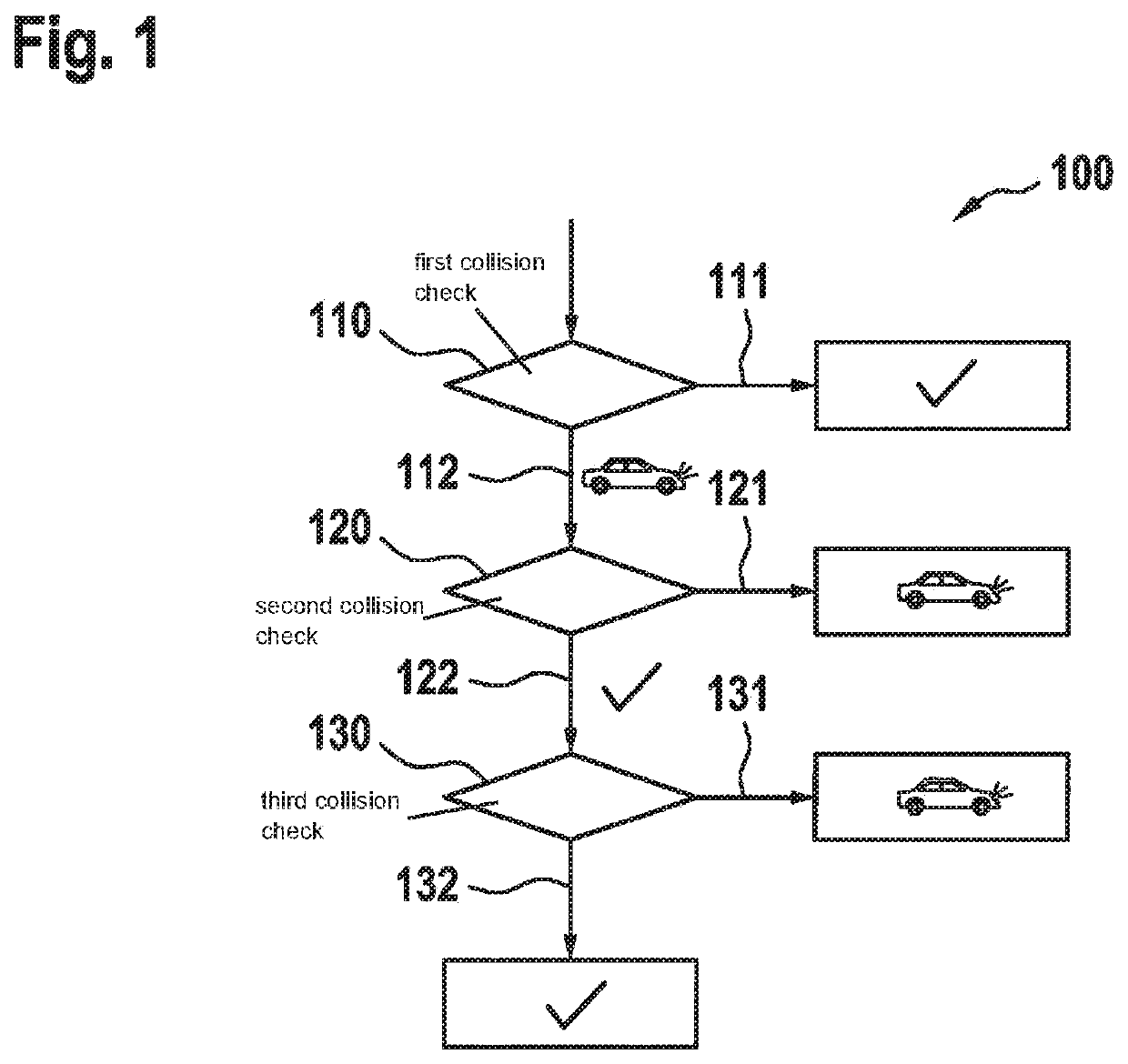
[0029]FIG. 1 shows a flow chart 100 illustrating an example method for detecting collisions for a vehicle 2 in a first specific embodiment of the present invention. In this first specific embodiment, the method is a three-stage method, in which a first collision check 110, a second collision check 120, and a third collision check 130 are performed.

[0030]The method is a step-by-step collision detection. This means that, under certain circumstances, a collision may already be ruled out once first collision check 110 is performed. Furthermore, once second collision check 120 is performed, a collision may already be determined with certainty in the case that the object, with which the collision would occur, is situated accordingly relative to the trajectory. Only in those cases where first collision check 110 and second collision check 120 do not yield a certain result is third collision check 130 performed to examine borderline cases.

[0031]The method begins with the execution of first ...


PUM


Abstract

A method and a device for detecting collisions for a vehicle. In this context, an at least three-stage method is described. A first collision check, a second collision check, and a third collision check are performed. Surface areas are considered step-by-step along a section of a trajectory of the vehicle. In the individual steps, the surface areas in the individual steps being approximated to the actual swath of the vehicle.

Description

FIELD[0001]The present invention relates to a method and a device for detecting collisions for a vehicle.BACKGROUND INFORMATION[0002]Maneuvering vehicles in close scenarios plays an important role especially when parking vehicles. The difficulty first lies in generating a collision-free trajectory that includes as few as possible changes in direction and minimal curvature changes over the course of the trajectory. To this end, geometric methods are mostly used.[0003]In the near future, high-density parking will be used for automated vehicles, i.e., the vehicles will be parked more closely together and possibly in a way that will require displacement operations to move a further vehicle out of a parking space. Resulting therefrom are highly non-convex state spaces within which a trajectory must be found for maneuvering the vehicle. Moreover, in such scenarios, the exact contour of the vehicle must be included in the planning, and it is not possible to refer merely to rectangular boun...

Claims


Application Information

Patent Timeline
Patent Type & Authority Patents(United States)
IPC IPC(8): B60W30/095G01V11/00
CPCG01V11/002B60W30/0956G08G1/165G08G1/166G08G1/168B60W30/0953B60W2554/00
Inventor BANZHAF, HOLGER ANDREAS
Owner ROBERT BOSCH GMBH
Why Eureka
Try Eureka