Wavelength dispersion amount estimation apparatus

Active Publication Date: 2022-05-19
NIPPON TELEGRAPH & TELEPHONE CORP
View PDF0 Cites 0 Cited by
  • Summary
  • Abstract
  • Description
  • Claims
  • Application Information

AI Technical Summary

Benefits of technology

The present invention allows for the quick and easy calculation of wavelength dispersion without needing a specific training signal. This results in significant efficiency and effectiveness in optical communication systems.

Problems solved by technology

Wavelength dispersion is the most common problem of signal distortion that is problematic in optical fiber communications.
There is also a technique in which the wavelength dispersion amount of the transmission line is measured in advance by a measurement device, but in this technique, costs are increased in tens of operation.

Method used


Image

  • Wavelength dispersion amount estimation apparatus
  • Wavelength dispersion amount estimation apparatus
  • Wavelength dispersion amount estimation apparatus

Examples


first embodiment

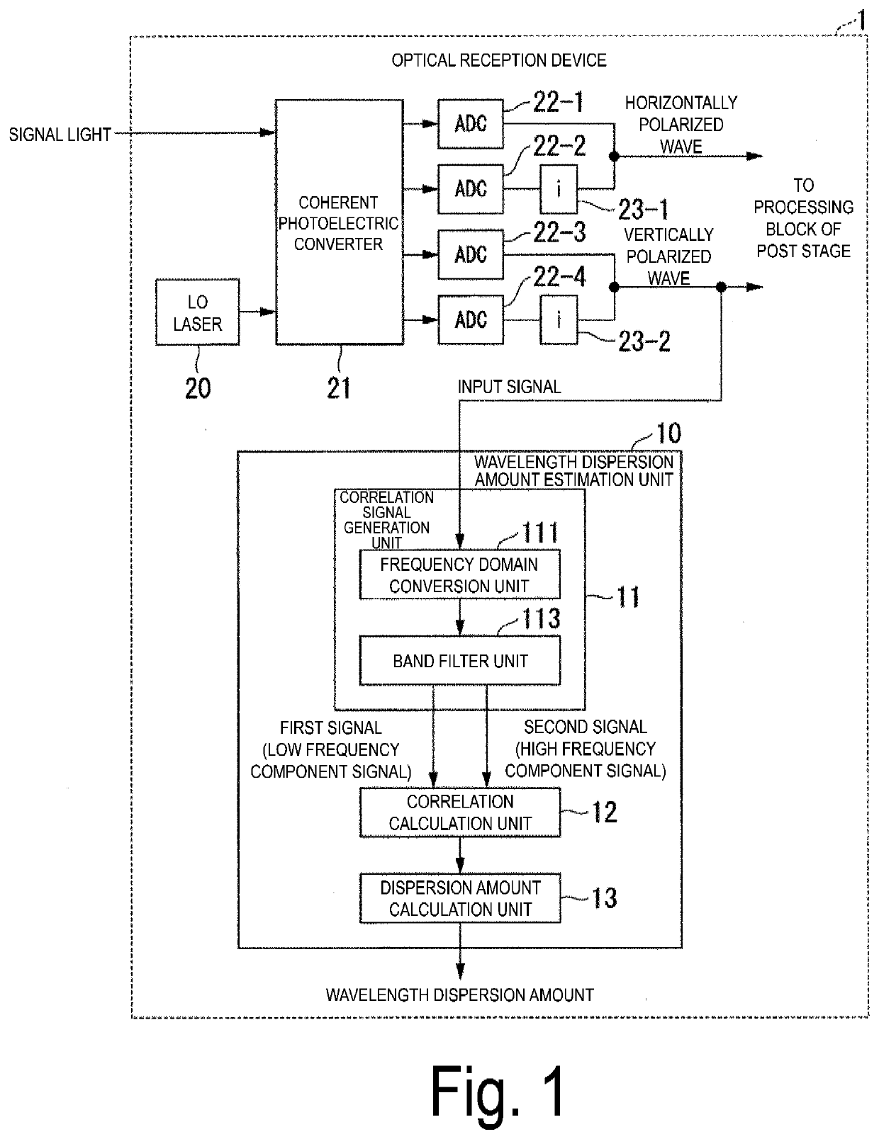
[0044]Embodiments of the present invention will be described below with reference to the drawings. FIG. 1 is a block diagram illustrating a configuration of an optical reception device 1 included in a wavelength dispersion amount estimation unit 10 according to a first embodiment. The optical reception device 1 is an optical reception device that receives signal light in a so-called digital coherent scheme and includes a local oscillator (LO) laser 20, a coherent photoelectric converter 21, analog-to-digital converters (ADCs) 22-1 to 22-4, imaginary unit multiplication units 23-1 and 23-2, and the wavelength dispersion amount estimation unit 10.

[0045]The LO laser 20 is a local oscillation laser, and outputs localized oscillating light having a phase matching the frequency of the signal light. The coherent photoelectric converter 21 uses the local oscillating light output by the LO laser 20 to perform optical homodyne coherent detection on the received signal light to convert the sig...

second embodiment

[0107]FIG. 14 is a block diagram illustrating a configuration of a wavelength dispersion amount estimation unit 10b according to a second embodiment.

[0108]The same components as those according to the first embodiment are denoted by the same reference signs, and different components will be described below.

[0109]In the wavelength dispersion amount estimation unit 10 or 10a according to the first embodiment, the band filter unit 113 selects the high frequency band section 130 and the low frequency band section 131 for a single FFT frame, and generates a high frequency component signal and a low frequency component signal. Then, the correlation calculation unit 12 multiplies, for each element, a complex conjugate of either the high frequency component signal or the low frequency component signal with the other signal, and converts the result into the time domain by the IFFT to calculate the cross correlation. In this way, in the calculated cross correlation, a peak appears at a single...

third embodiment

[0133]FIG. 17 is a block diagram illustrating a configuration of a wavelength dispersion amount estimation unit 10c according to a third embodiment.

[0134]The same components as those according to the first embodiment are denoted by the same reference signs, and different components will be described below. The wavelength dispersion amount estimation unit 10c includes a correlation signal generation unit 11c, a correlation calculation unit 12c, and a dispersion amount calculation unit 13c. The wavelength dispersion amount estimation unit 10, 10a or 10b according to the first and second embodiments generates a signal for cross correlation in the frequency domain. In contrast, the wavelength dispersion amount estimation unit 10c according to the third embodiment generates a signal for cross correlation in the time domain.

[0135]The correlation signal generation unit 11c includes a branching device 115, an oscillator 116, a complex conjugate computation unit 117, multipliers 118-1 and 11...


PUM


Abstract

A wavelength dispersion amount estimation apparatus includes a correlation signal generation unit configured to generate, from a receive signal, a first signal including a main signal of the receive signal and a second signal, which includes an image signal corresponding to the main signal, with a shift by a baud rate of the receive signal relative to the first signal in a frequency domain, a correlation calculation unit configured to calculate a cross correlation of the first signal and the second signal, and a dispersion amount calculation unit configured to calculate a wavelength dispersion amount, based on a position of a peak of the cross correlation.

Description

TECHNICAL FIELD[0001]The present invention relates to a wavelength dispersion amount estimation apparatus.BACKGROUND ART[0002]Wavelength dispersion is the most common problem of signal distortion that is problematic in optical fiber communications. Wavelength dispersion is caused by the difference in the group velocities of signal light beams propagating in an optical fiber depending on the frequency. Because the signal distortion due to wavelength dispersion is linear distortion, if the wavelength dispersion amount is known, it is nearly possible to completely compensate the signal distortion by providing an inverse wavelength dispersion. The application of the inverse wavelength dispersion is done with a dispersion compensation fiber in the case of a direct detection scheme, but is mainly done in digital signal processing in the case of digital coherent reception schemes.[0003]In a case in which the wavelength dispersion amount is not known, it is necessary to measure or estimate ...

Claims


Application Information

Patent Timeline
IPC IPC(8): H04B10/2507
CPCH04B10/2507H04B10/07951
Inventor HORIKOSHI, KENGONAKAMURA, MASANORIKISAKA, YOSHIAKIOKAMOTO, SEIJIHAMAOKA, FUKUTARO
Owner NIPPON TELEGRAPH & TELEPHONE CORP
Why Eureka
Try Eureka