
Backlight partition driving module, backlight device, and display device

a backlight partition and driving module technology, applied in the field of display technology, can solve the problems of increased product cost and limited achieve the effects of increasing the number of backlight partitions, improving flexibility and universality of the backlight partition driving module, and reducing the number of backlight partition driving modules

Active Publication Date: 2022-02-15
TCL CHINA STAR OPTOELECTRONICS TECH CO LTD
View PDF16 Cites 0 Cited by
  • Summary
  • Abstract
  • Description
  • Claims
  • Application Information

AI Technical Summary

Benefits of technology

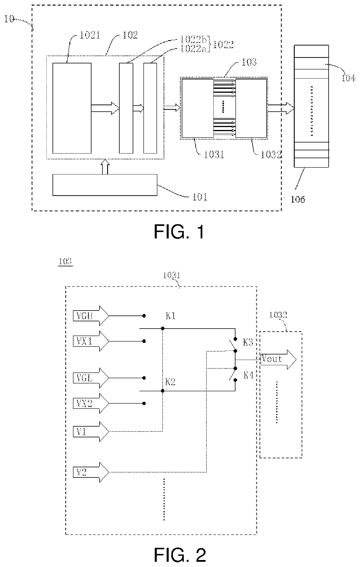
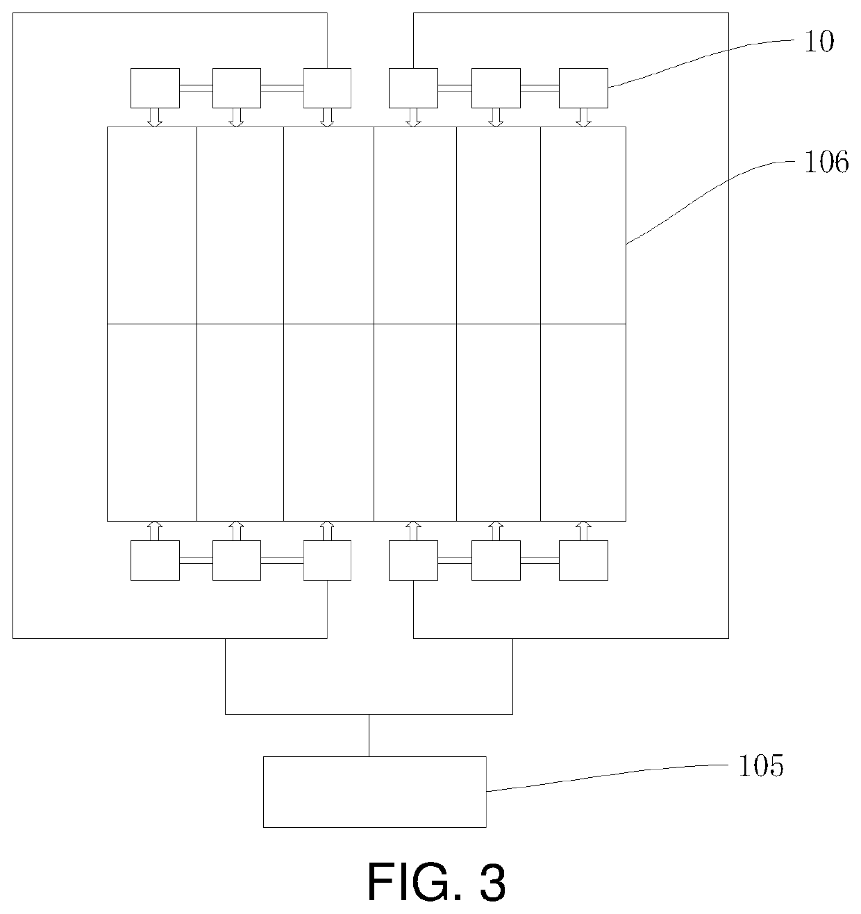
The patent provides a solution to the technical problem of increased costs and limited backlight part options in local dimming technology. The solution involves a driving module that can select and turn on each group of drive signals to the corresponding scanning line or data line. This means that multiple backlight partitions can share one driving module, which improves flexibility and reduces the number of driving modules needed. This results in increased backlight partitions and reduced costs.

Problems solved by technology

An embodiment of the present disclosure provides a driving module, a backlight device, and a display device to solve a technical problem that current local dimming technology requires a greater number of driving modules due to a greater number of backlight partitions, resulting in increased product costs and limited number of backlight partitions.

Method used


Image

  • Backlight partition driving module, backlight device, and display device
  • Backlight partition driving module, backlight device, and display device

Examples


Embodiment Construction

[0027]The technical solutions in the embodiments of the present disclosure will be clearly and completely described below in conjunction with accompanying drawings in the embodiments of the present disclosure. Obviously, the embodiments described are merely a part of the present disclosure, rather than all the embodiments. All other embodiments obtained by the person having ordinary skill in the art based on embodiments of the disclosure, without making creative efforts, are within the scope of the present disclosure.

[0028]In descriptions of the present disclosure, it should be noted that, orientations or position relationships indicated by the terms, such as “center”, “longitudinal”, “transverse”, “length”, “width”, “thickness”, “upper”, “lower”, “front”, “back”, “left”, “right”, “vertical”, “horizontal”, “top”, “bottom”, “inside”, “outside”, “clockwise”, “counterclockwise”, etc. are based on the orientations or position relationships shown in the drawings. These are only convenien...


PUM


Abstract

The present invention provides a backlight partition driving module, a backlight device, and a display device which include a signal input module configured to receive a driving signal, wherein the driving signal includes a brightness data signal, a scanning signal, and a function signal; a signal transmission module transmitting the driving signal; and a selection output module receiving the driving signal and is configured to output the scanning signal to a scanning line or the brightness data signal to a data line under control of the function signal.

Description

FIELD OF INVENTION[0001]The present disclosure relates to the field of display technology, and more particularly, to a backlight partition driving module, a backlight device, and a display device.BACKGROUND OF INVENTION[0002]With vigorous development of an information society, driving technology of the display panel manufacturing industry has matured, and opportunities and challenges will follow. Due to limitations of liquid crystal display (LCD) backlight, such as high-power consumption and low contrast, the backlight is forced to develop in a direction of local dimming.[0003]Current mini light-emitting diode (mini-LED) backlights adopt a static driving scheme or a passive matrix (PM) driving scheme to realize the local dimming of the backlight. Moreover, due to a greater number of backlight partitions, each backlight partition requires a data line for signal transmission, resulting in an excessive number of lines and driving modules, and a certain space for layout, which increases...

Claims


Application Information

Patent Timeline
Patent Type & Authority Patents(United States)
IPC IPC(8): G09G3/34
CPCG09G3/342G09G2310/027G09G2310/0267G09G2320/0626
Inventor WANG, FUYIJOU, MINGJONGWANG, ZHAOXU, FENGCHENGLIU, JINFENG
Owner TCL CHINA STAR OPTOELECTRONICS TECH CO LTD
Learn More