Photovoltaic module mounting system

a technology for photovoltaic modules and mounting systems, applied in photovoltaic supports, heat collector mounting/supports, light and heating equipment, etc., can solve the problems of increasing the complexity and cost of installation, affecting the aesthetics of installation, and the module edges cannot be placed close to each other

Active Publication Date: 2022-02-15
LUMOS SOLAR
View PDF4 Cites 0 Cited by
  • Summary
  • Abstract
  • Description
  • Claims
  • Application Information

AI Technical Summary

Problems solved by technology

In addition, adjustments as to the position of each module is often required which is time consuming and increases the complexity and cost of installation.
Therefore, the module edges cannot be placed in close proximity to each other.
Such a mounting system also leaves exposed the mounting hardware and rails which negatively affects the aesthetics of an installation.

Method used


Image

  • Photovoltaic module mounting system
  • Photovoltaic module mounting system
  • Photovoltaic module mounting system

Examples


Embodiment Construction

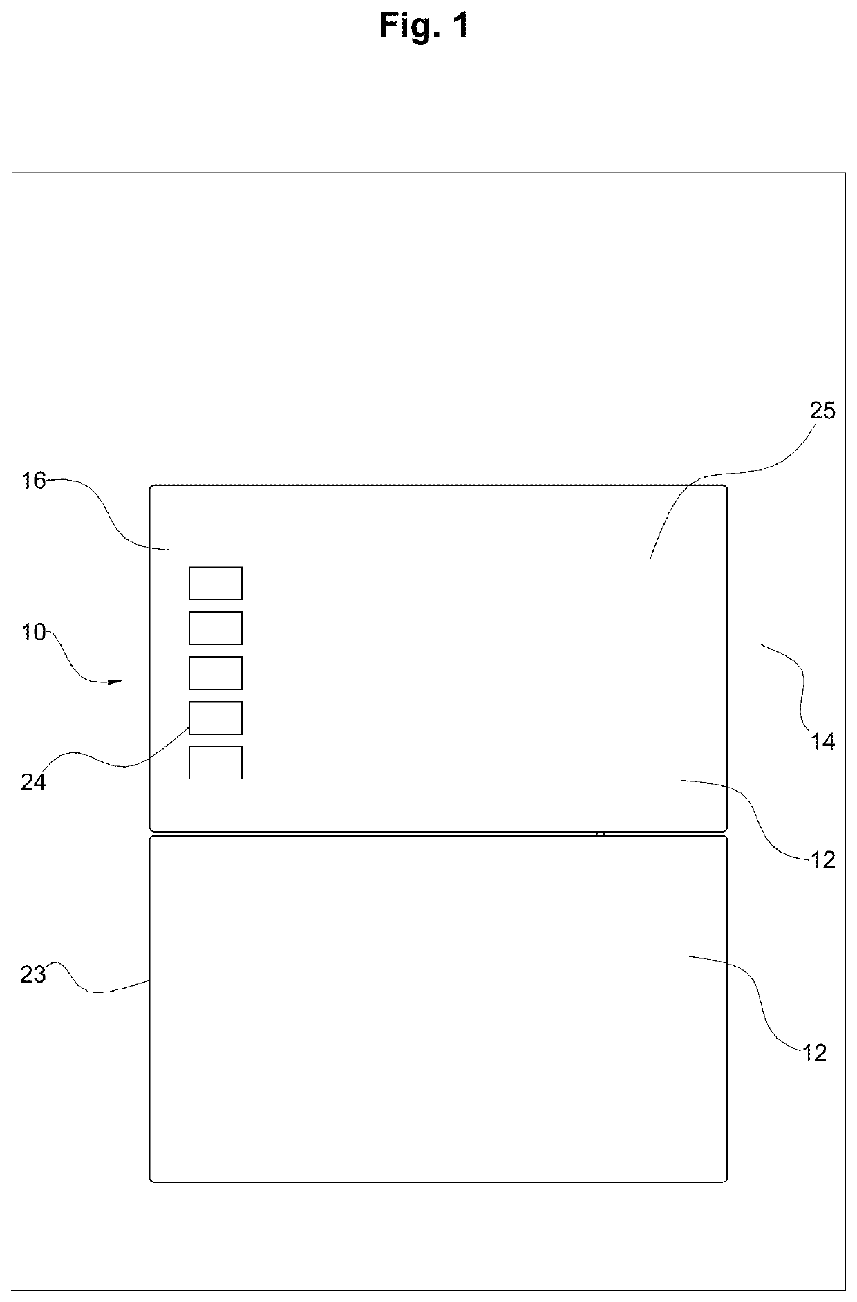
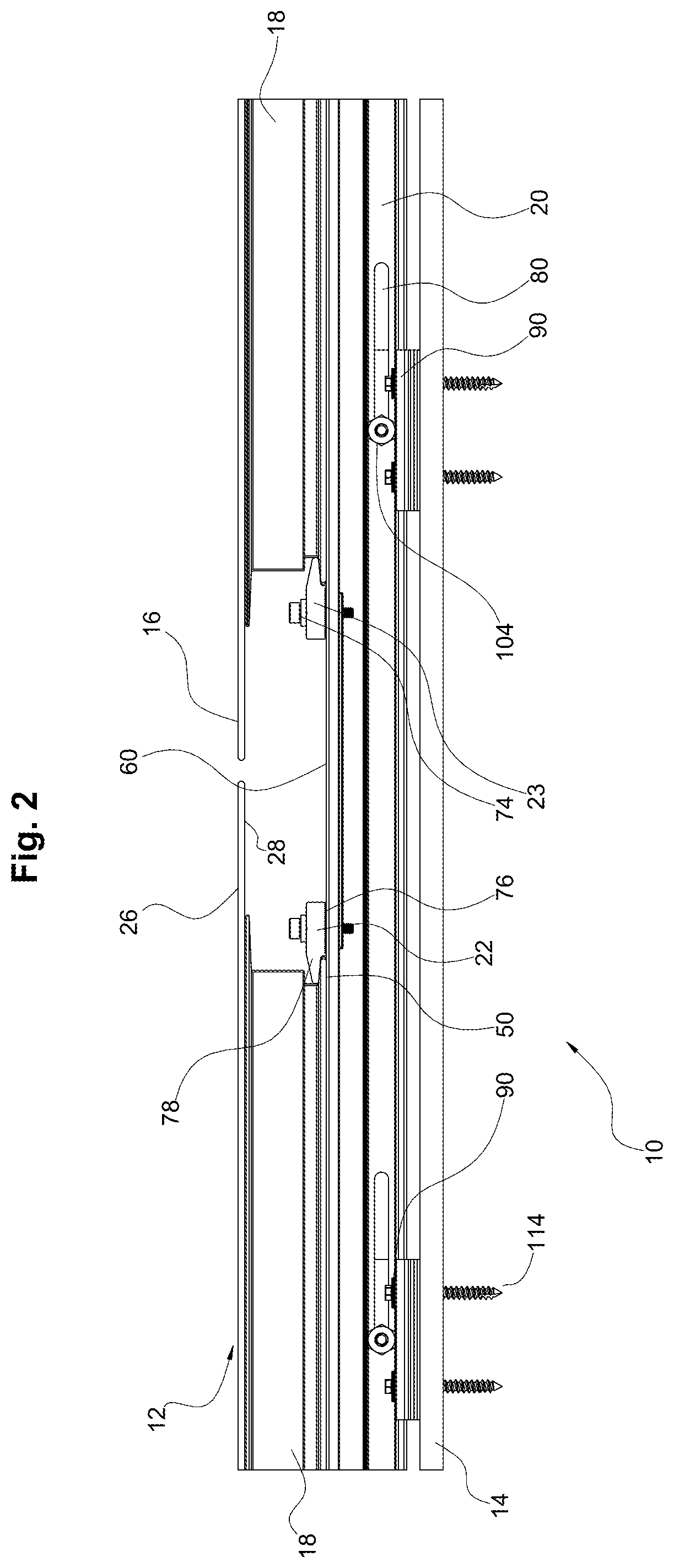
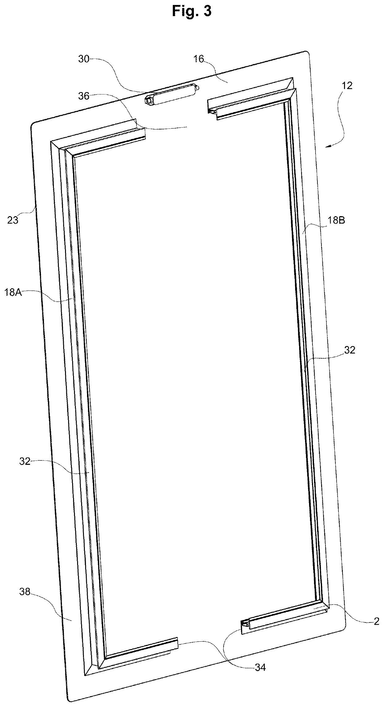
[0021]With reference to FIGS. 1-3, the photovoltaic (“PV”) module mounting system 10 of the present disclosure permits PV modules 12 to be efficiently and securely mounted to a support structure 14. The system 10 includes one or more PV modules 12 which include a PV panel 16 having a mounting frame 18 secured to the bottom thereof. The system further includes a plurality of mounting rails 20 having retainers 22 that securely fasten the PV modules 12 to the rails.

[0022]With reference to FIGS. 1, 3 and 4, the PV module 12 includes a generally planar PV panel that is bounded by a perimeter 23 formed of a plurality of interconnecting edges. The PV panel includes a plurality of photovoltaic cells 24 for generating electricity. The PV module 12 includes a top surface 26 which is faced toward the sun and may be formed of a transparent material such as glass that covers the photovoltaic cells 24. Opposite the top surface is a bottom surface 28 to which the mounting frame 18 is secured. The ...


PUM

PropertyMeasurementUnit
perimeteraaaaaaaaaa
distanceaaaaaaaaaa
heightaaaaaaaaaa

Abstract

A photovoltaic mounting system including a photovoltaic module having a panel having an upper surface including a plurality of photocells and an opposed bottom surface, the module being bounded by a perimeter edge. A mounting frame is secured to the bottom surface of the module. The mounting frame is offset from each of the perimeter edges of the module. The mounting frame includes an upper surface secured to the module and an opposed lower end having a mounting projection.

Description

[0001]This application claims the benefit of priority to U.S. Provisional Application Ser. No. 62 / 372,566 filed on Aug. 9, 2016 the content of which is incorporated by reference herein in its entirety.FIELD OF INVENTION[0002]The present invention relates to a system and method for securing modules and more particularly to a system and method for securing photovoltaic modules to a structure.BACKGROUND OF THE INVENTION[0003]Photovoltaic (“PV”) modules, also known as solar modules, are well known in the art for converting solar energy into electrical energy. As the desirability for clean and efficient energy sources increases, so does the desire to use power sources such as PV modules.[0004]PV modules are typically mounted on a structure, such as a roof of a house or building where they are readily exposed to sunlight. Since the modules are exposed to the environment, they need to be properly secured to the structure so they can withstand winds and other environmental effects. Photovol...

Claims


Application Information

Patent Timeline
Patent Type & Authority Patents(United States)
IPC IPC(8): H02S30/10H02S20/23F24S25/636F24S25/632
CPCH02S30/10F24S25/632F24S25/636H02S20/23Y02B10/10Y02E10/47Y02E10/50
Inventor FRANKLIN, SCOTTRAFFERTY, BRIANYZQUIERDO, KEITH
Owner LUMOS SOLAR
Why Eureka
Try Eureka