
Roof photovoltaic support structure system without counterweight foundation

A photovoltaic bracket without counterweight technology, which is applied to the support structure of photovoltaic modules, the fixed base/support of solar collectors, photovoltaic modules, etc., and can solve the problems of increasing roof load, roof panel thickness or reinforcement Large project cost and other issues, to achieve the effect of improving installation efficiency, long service life, easy disassembly and assembly

Active Publication Date: 2022-03-01
中石化石油工程技术服务有限公司 +1
View PDF15 Cites 0 Cited by
  • Summary
  • Abstract
  • Description
  • Claims
  • Application Information

AI Technical Summary

Problems solved by technology

Disadvantages: Option 1 will greatly increase the roof load, resulting in an increase in the thickness of the roof panel or the amount of reinforcement, increasing the cost of the project; if the photovoltaic system is added to the existing roof, due to the large increase in load, it will often exceed the original roof design Carrying capacity, which in turn prevents the project from proceeding
The installation of embedded parts in Option 2 will lead to difficulties in the construction of the roof surface in the later stage, and will also affect the effect of the roof waterproof layer; if the photovoltaic system is added to the existing roof and anchored by setting expansion bolts, the original roof will inevitably be damaged Insulation and waterproofing

Method used


Image

  • Roof photovoltaic support structure system without counterweight foundation
  • Roof photovoltaic support structure system without counterweight foundation
  • Roof photovoltaic support structure system without counterweight foundation

Examples


Embodiment Construction

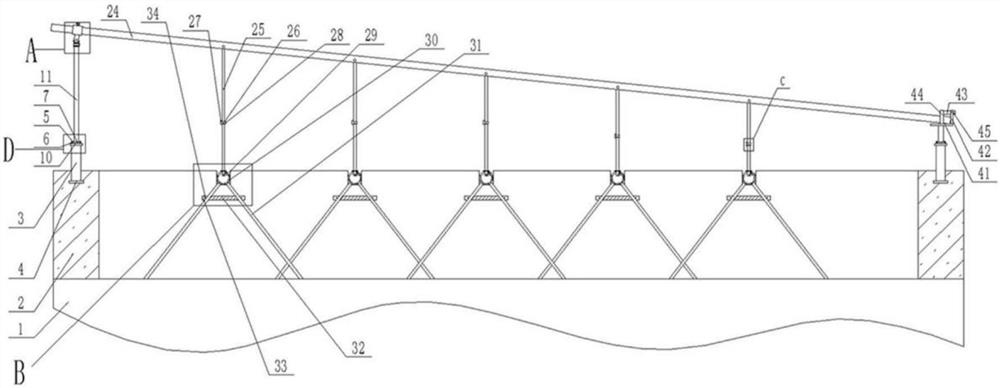
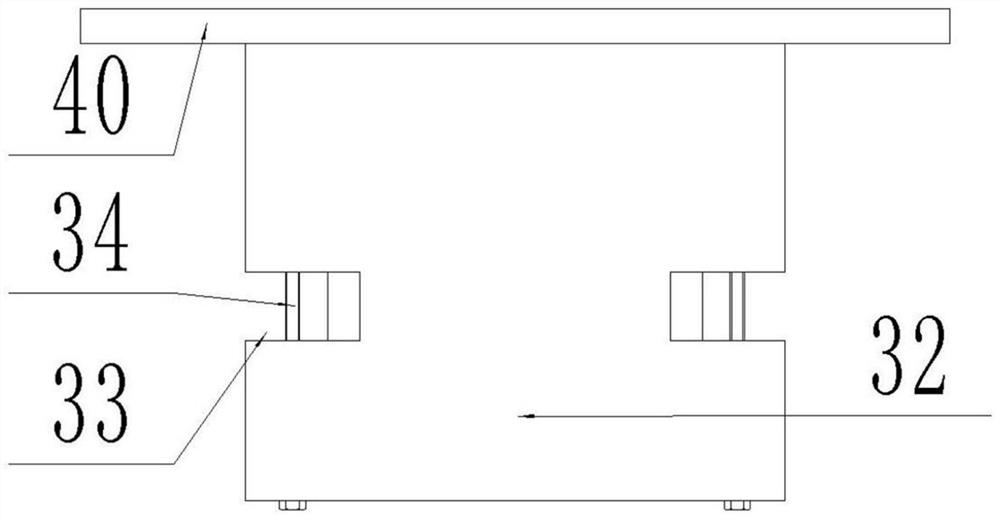
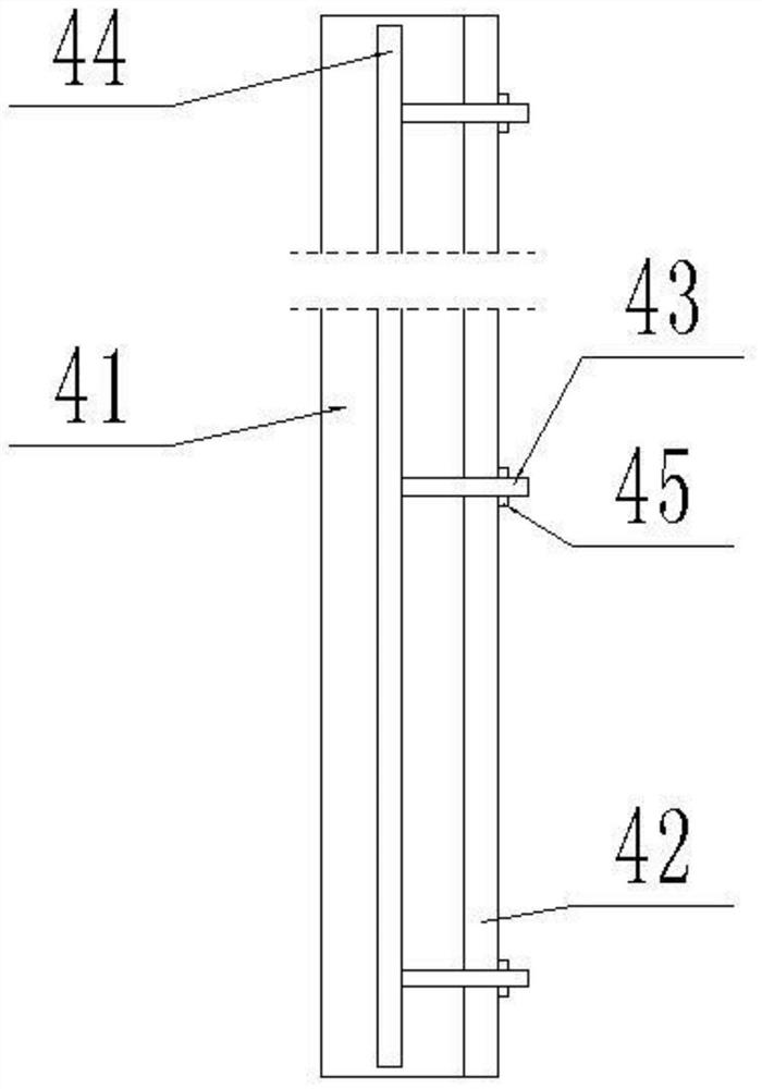
[0030] Such as figure 1 , 3 , 4, 5, and 6, a roof photovoltaic support structure system without a counterweight foundation includes a house body 1, and a parapet 2 is arranged on the roof of the house body 1, and the parapet 2 is formed by pouring concrete. The parapets 2 on the left and right sides are pre-buried and fixed with a plurality of embedded parts, and the plurality of embedded parts are arranged vertically and evenly, and the embedded parts on the left and right are in one-to-one correspondence, and the embedded parts include Vertical pre-embedded rod 3, the upper end and the lower end of pre-embedded rod 3 are respectively fixed with fixed plate 10 and base plate 4, and base plate 4 and pre-embedded rod 3 lower parts are pre-embedded and fixed in parapet 2. The upper end of the embedded part is connected with a vertical ejector rod 11 through a quick-installation device, the ejector rod 11 on the left is higher than the ejector rod 11 on the right, and the upper ...


PUM


Abstract

The invention relates to the field of roof photovoltaic installation systems, in particular to a roof photovoltaic support structure system without a counterweight foundation. Comprising a house body, parapet walls are arranged on a roof of the house body, a plurality of embedded parts are fixed to the parapet walls on the left side and the right side in an embedded mode, vertical ejector rods are connected to the upper ends of the embedded parts through quick mounting devices, the ejector rods on the left side are higher than the ejector rods on the right side, and the upper ends of the ejector rods on the left side are connected with the left ends of supporting rods through first positioning devices; the upper end of the right ejector rod is connected with the right end of the supporting rod through a second positioning device, a plurality of supporting rods are connected to the portion, between the left ejector rod and the right ejector rod, of the supporting rod, and supporting devices corresponding to the supporting rods are arranged on the roof of the house body. The device is convenient to disassemble and assemble, does not need to add a balance weight, does not need to damage a waterproof layer of a roof, does not need too many loose parts in the installation process, can improve the installation efficiency, is long in service life, can recover the supporting rods into the supporting rods, and is convenient to hoist.

Description

technical field [0001] The invention relates to the field of a roof photovoltaic installation system, in particular to a roof photovoltaic support structure system without a counterweight foundation. Background technique [0002] For the anchoring of photovoltaic support on the roof, there are currently two main solutions; 1) Set a counterweight foundation on the column of the photovoltaic support, mostly a concrete cube or cylindrical support pier, anchor the photovoltaic system by its own weight, and resist the wind load. 2) Set up embedded parts or expansion bolts to connect with the roof structure layer to anchor the photovoltaic system. Disadvantages: Option 1 will greatly increase the roof load, resulting in an increase in the thickness of the roof panel or the amount of reinforcement, increasing the cost of the project; if the photovoltaic system is added to the existing roof, due to the large increase in load, it will often exceed the original roof design Carrying c...

Claims


Application Information

Patent Timeline
IPC IPC(8): E04D13/14E04B1/41H02S20/23F24S25/61
CPCE04D13/14E04B1/41H02S20/23F24S25/61E04D2013/1422Y02E10/47Y02E10/50Y02B10/10Y02B10/20
Inventor 刘浩仝淑月韦建中曾飞张哲高培楠时晓晔孙鹏辉
Owner 中石化石油工程技术服务有限公司
Learn More