Photovoltaic mounting system with grounding bars and method of installing same

a technology of photovoltaic mounting system and mounting rail, which is applied in the direction of heat collector mounting/support, connection contact material, lighting and heating apparatus, etc., can solve the problems of preventing the energized frame from being energized, and ensuring the continuity of frame grounding,

Inactive Publication Date: 2014-08-07
GENERAL ELECTRIC CO
View PDF6 Cites 1 Cited by
  • Summary
  • Abstract
  • Description
  • Claims
  • Application Information

AI Technical Summary

Benefits of technology

[0007]The inventors of the present application have solved the problem of assuring proper alignment of PV modules, while providing adequate grounding of the metal rail segments of the PV mounting system and a connector box that is attached to an end of an individual rail segment.

Problems solved by technology

A failure in the insulating material of the PV laminate could allow the frame to be energized up to 600V dc.
Because the modules in a typical PV array have aluminum frames that are often anodized, providing continuity of frame grounding does not ensure rail grounding and at least #10 gauge copper ground leads are required to be attached to each separate rail section and brought to a common point.

Method used


Image

  • Photovoltaic mounting system with grounding bars and method of installing same
  • Photovoltaic mounting system with grounding bars and method of installing same
  • Photovoltaic mounting system with grounding bars and method of installing same

Examples


Embodiment Construction

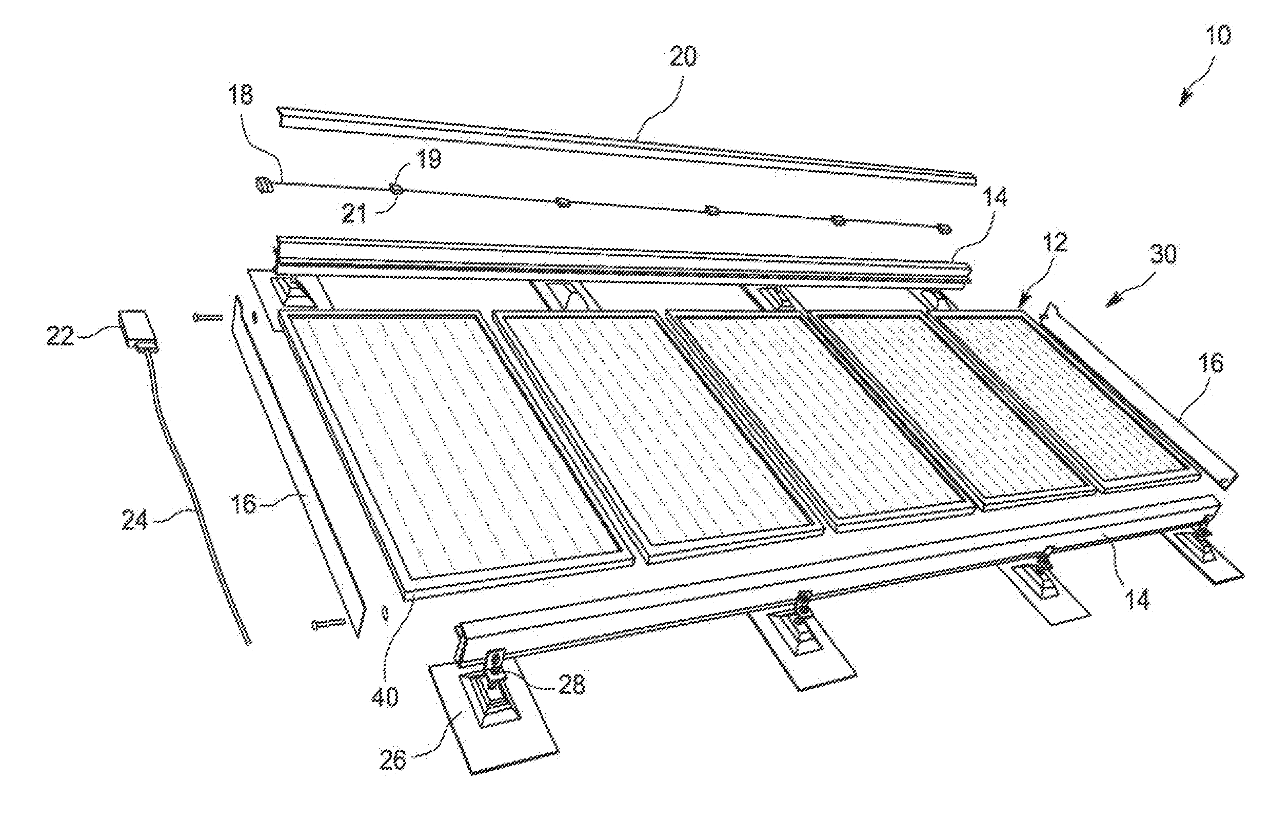
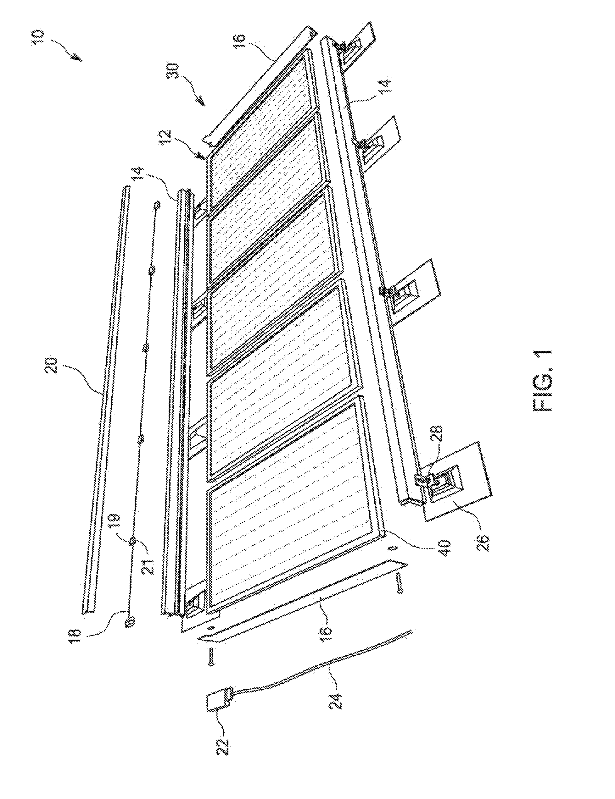
[0017]Referring now to FIGS. 1-5, a photovoltaic (PV) mounting system 10 includes a plurality of PV modules 12, a plurality of metallic rail sections 14, a plurality of metallic grounding bars 16, a wiring harness 18, a locking cover 20 for covering and protecting the wiring harness 18, a connector box 22, at least one home run cable 24, and a plurality of mounting stanchions 26 with L-brackets 28 for mounting the rails sections 14 to the stanchions 26. In the illustrated embodiment, the PV mounting system 10 includes a basic building block 30 with five (5) PV modules 12. However, it will be appreciated that the invention is not limited by the number of PV modules 12 that are configured for the basic building block 30, and that the basic building block 30 may include any desirable number of PV modules 12, depending on design requirements and National Electrical Code (NEC) limitations. In one example, each PV module 12 is an ac module consisting of a low voltage dc module and an inte...


PUM

PropertyMeasurementUnit
voltagesaaaaaaaaaa
dc voltageaaaaaaaaaa
ac-voltage aaaaaaaaaa

Abstract

A photovoltaic (PV) mounting system includes at least one PV module, a pair of metallic rail sections, and a grounding bar connected to each end of the metallic rail sections for grounding the metallic rail sections. The system also includes a wiring harness for electrically connecting several PV modules, a locking cover for covering and protecting the wiring harness, a standard connector box electrically connected to one end of the wiring harness, and a home run cable electrically connected to the connector box. A method for grounding the PV mounting system is also disclosed.

Description

CROSS-REFERENCE TO RELATED APPLICATION[0001]The present application is a continuation of and claims priority to U.S. patent application Ser. No. 13 / 079,900, filed Apr. 5, 2011, the disclosure of which is incorporated herein by reference.BACKGROUND[0002]The invention relates generally to photovoltaic (PV) systems and more particularly to a system and method for grounding PV mounting system and rail sections.[0003]Nearly all electrical systems in the U.S. are grounded to mitigate the impacts of lightning, line surges, or unintentional contact with high voltage lines. Most PV systems include modules with metal frames and metal mounting racks that are in exposed locations, e.g. rooftops where they are subject to lightning strikes, or are located near high voltage transmission lines that in the event of high winds, etc., can come into contact with PV arrays.[0004]The modules in a typical PV array have aluminum frames that are often anodized. The 2008-NEC code that has the same requiremen...

Claims


Application Information

Patent Timeline
Patent Type & Authority Applications(United States)
IPC IPC(8): H01L31/042
CPCH01L31/0424Y02B10/20H01R4/64Y02E10/47H02S30/10H02S20/23H02S40/34F24S25/35Y10T29/49117Y02E10/50Y02B10/10
Inventor KORMAN, CHARLES STEVENJOHNSON, NEIL ANTHONYWAGNER, CHRISTIAN JOSEPH
Owner GENERAL ELECTRIC CO
Why Eureka
Try Eureka