Stopper for bottles

Active Publication Date: 2022-03-22
BETAPACK
View PDF23 Cites 0 Cited by
  • Summary
  • Abstract
  • Description
  • Claims
  • Application Information

AI Technical Summary

Benefits of technology

[0016]Furthermore, the closing cap advantageously comprises a closing collar that is engaged to a nozzle of the pouring element, said closing collar comprising a recess in the area closest to the hinge between the pouring element and the closing cap. This recess facilitates the engagement between the closing colla

Problems solved by technology

It is usual for the user to drink directly from the bottle when using this type of st

Method used


Image

  • Stopper for bottles
  • Stopper for bottles

Examples


Embodiment Construction

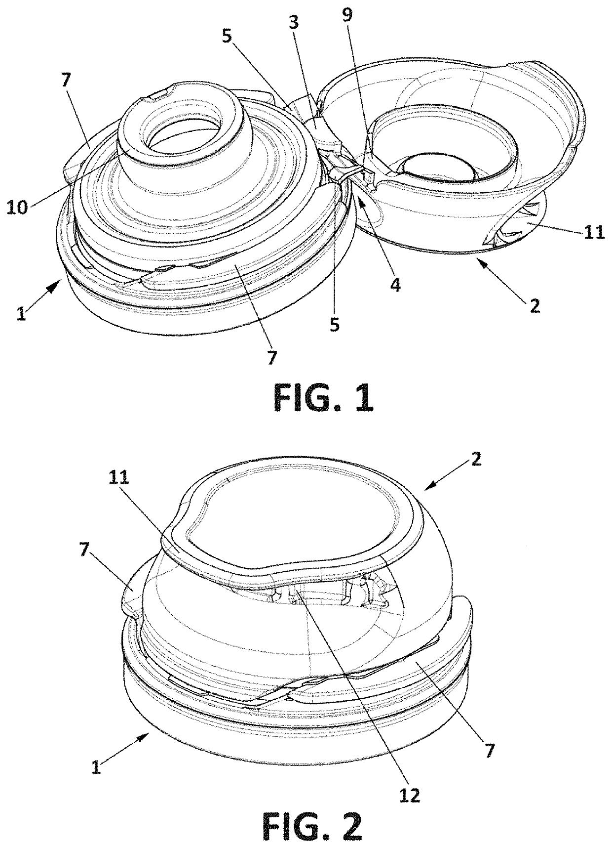
[0022]As shown in the figures, the stopper for bottles according to the present invention comprises a pouring element, generally identified by reference number 1, and a closing cap, generally identified by reference number 2.

[0023]The pouring element 1 is attached to the neck of a bottle, not shown, for example, by an engaging thread or cord. This pouring element 1 is designed so that during its normal use it does not separate from the bottle.

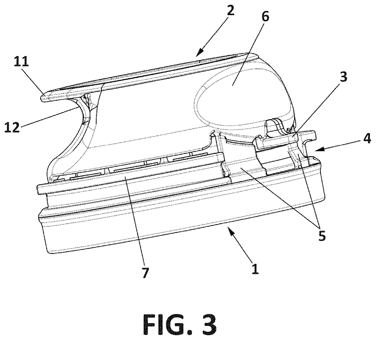
[0024]On the other hand, the closing cap 2 is mounted hinged to said pouring element 1 by means of a hinge 4, and it can be placed in an open position (shown in FIG. 1) or in a closed position (shown in FIGS. 2 and 3).

[0025]According to the present invention, the stopper for bottles comprises a protrusion 3 in its closest part to the pouring element 1, as can be seen in the figures. This protrusion 3 contacts the pouring element 1 in the open position of the closing cap 2. For example, this protrusion 3 contacts a circular wall of the pouring e...


PUM


Abstract

Stopper for bottles, comprising a pouring element (1) assembled with a hinged closing cap (2), the closing cap (2) being able to be placed in an open position and a closed position, characterized in that said closing cap (2) comprises a protrusion (3) in its closest part to the pouring element (1), whose protrusion (3) contacts the pouring element (1) in the open position of the closing cap (2).

Description

CROSS-REFERENCE TO RELATED APPLICATIONS[0001]This application is a 371 PCT national application claiming priority to PCT / ES2017 / 070800, filed Dec. 7, 2017, having the same title and inventor, and which is incorporated herein by reference in its entirety.DESCRIPTION[0002]The present invention relates to a stopper for bottles, comprising a pouring element assembled with a hinged closing cap for its engagement to the neck of a bottle.BACKGROUND OF THE INVENTION[0003]The use of stoppers for the closure of bottles is common. One type of these stoppers is formed by a pouring element assembled with a hinged closing cap that is attached to the neck of the bottle and a closing cap that serves to close the bottle. This pouring element and the closing cap are hinged with each other by means of a hinge, so that the user can open and close the bottle by articulating the cap backwardly of the pouring element to open the bottle and articulating the cap forwardly to re-close the bottle.[0004]This t...

Claims


Application Information

Patent Timeline
IPC IPC(8): B65D47/08B65D51/24
CPCB65D47/0838B65D51/242B65D2203/12B65D2251/1008
Inventor BERROA GARCIA, JAVIER
Owner BETAPACK
Why Eureka
Try Eureka